Kerrie Wu
Kerrie Wu
I'm interested in autonomous systems and assistive/medical technology. Currently working on autonomous driving at Waymo. Please let me know if you'd like to get in touch!
wukerrie[at]gmail[dot]com
Questions? Email me!
Work Experience
-
Systems Engineer at Waymo
Sept 2020 - present• Autonomous driving performance analyses and vehicle model verification.
-
Systems Test Engineer at Waymo
Nov 2018 - Sept 2020• Test automation, coordination, and execution for ensuring safety and performance of autonomous driving systems.
-
Undergraduate Research Assistant at MIT CSAIL
Feb-May 2018• Build an annotated roadgraph in Python for autonomous driving simulation to demonstrate road rules compliance.
-
Controls Intern at Cruise Automation
Jun-Aug 2017• Prototyped algorithms for improving control performance. Wrote bulk data processing scripts for autonomous cars.
-
Intern at NASA Jet Propulsion Lab
Jun-Aug 2016• Designed, built, operated an automated imaging testbed for evaluating an image registration algorithm’s performance for the Mars 2020 Rover, collecting more than 1600 images. Analyzed algorithm performance using the dataset.
• Authored abstract for submission to International Workshop on Instrumentation for Planetary Missions.
-
Undergraduate Research Assistant at MIT Little Devices Lab
Oct 2015-Jan 2016• Designed and programmed a do-it-yourself usage-tracking/alarmed pill bottle construction set.
• Taught youth in a New York City STEM outreach program how to build the DIY pill bottle at a workshop.
-
Undergraduate Research Intern at Harvard Biodesign Lab
Jun-Aug 2015• Implemented and evaluated accuracy of an algorithm for calculating human rehabilitation-relevant gait parameters from inertial measurement units, compared to motion capture data.
-
Winter Extern at Boston Medical Center
Jan 2015• Shadowed medical physicist in clinical setting, observing interactions with physicians, therapists, and technicians, and use of relevant software for Cyberknife radiation therapy dose planning.
-
Research Intern at Sandia National Laboratories
Apr 2013-Jul 2014• Contributed to research utilizing microfluidic devices to investigate protein behavior at nanoconstrictions.
• Research was published in ACS Applied Materials and Interfaces.
Community/Leadership
-
East Campus Dorm Residential Exploration Chair
Feb-Sept 2016• Supported dozens of events and several large construction projects for my dorm’s freshman welcome week, including $20k+ budget, in a team of three students.
• Acted as liaison between offices (such as MIT EHS, Professional Engineer, City of Cambridge) and student design teams for construction projects such as a three-story tall wood structure, a swing carousel ride, and more.
-
Summer High School Studies Program Co-Director
May-Aug 2015• Recruited/interviewed teachers, coordinated student registration, and managed logistics for annual six-weekend summer program, serving over 800 middle and high school students from the local Boston Area.
-
Boston Serviceworks Volunteer
March 2017• Volunteered with Boston Cares: Serviceworks to run outreach activities with Boston public high school students as part of MIT’s Alternative Spring Break program.
Awards
Tuomala Award for Excellence in Thermal-Fluids Engineering, 2017
Whitelaw Prize for Originality and Creativity in Design, 2016
Education
-
Massachusetts Institute of Technology
2014-2018B.S., Engineering with concentration in Control, Instrumentation, and Robotics, 2018
-
Mission San Jose High School
2010-2014Valedictorian and National Merit Scholar
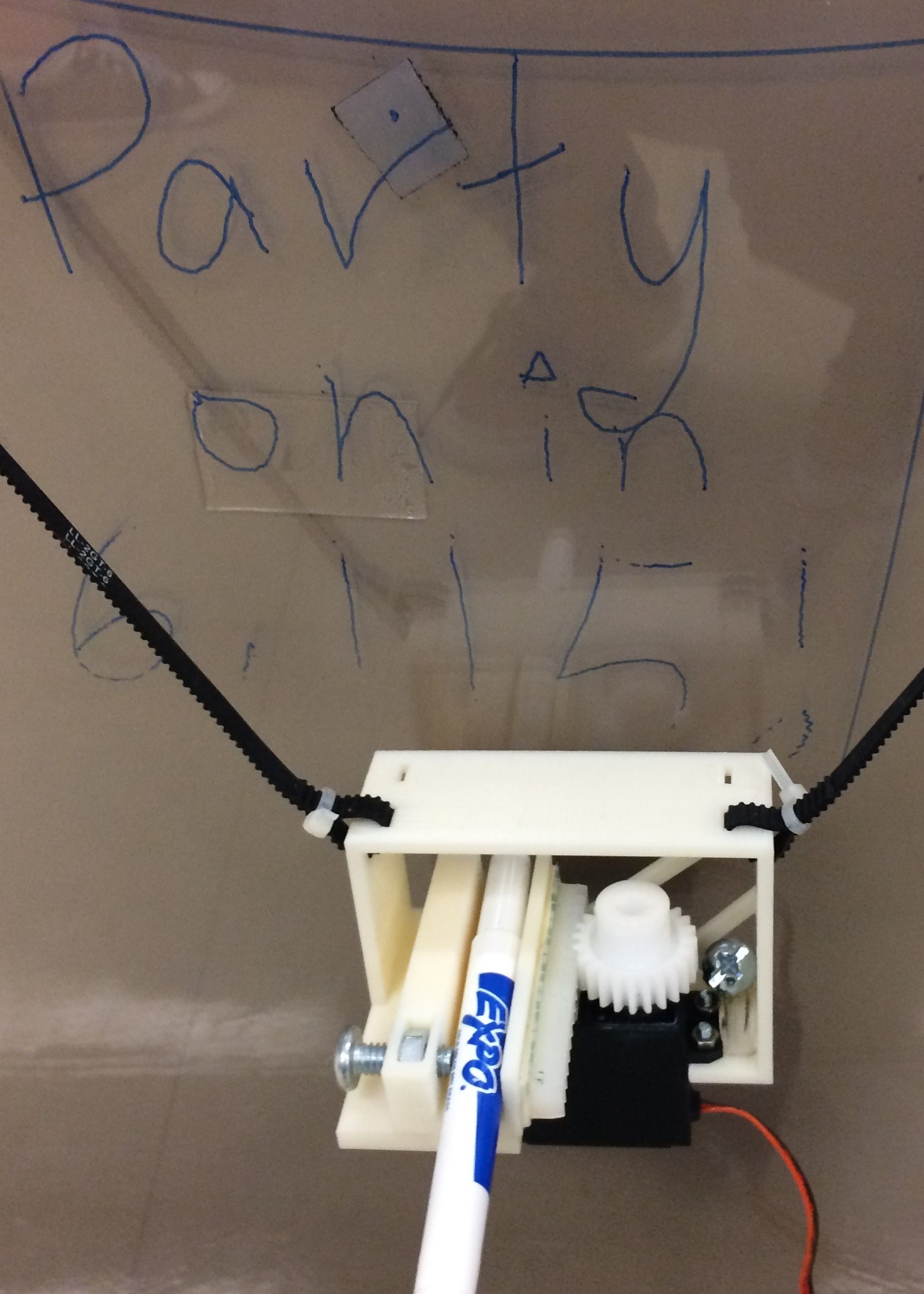
Hanging Wall Plotter
I built a hanging V-wall plotter as a final project for 6.115, a lab course I took on microcomputers. A couple hard requirements for the project were: (1) it must use an 8051 microcontroller, programmed in assembly, and (2) it must also use the Cypress PSoC. Otherwise, I had free reign to build/program anything I wanted within a 3-week timeframe. I had an broken deltaprintr lying around and wanted to make use of the stepper motors + drivers, so I decided to make a V-plotter.
Here's a video demonstration of the final product, writing "Hello" on a piece of acrylic with whiteboard marker.
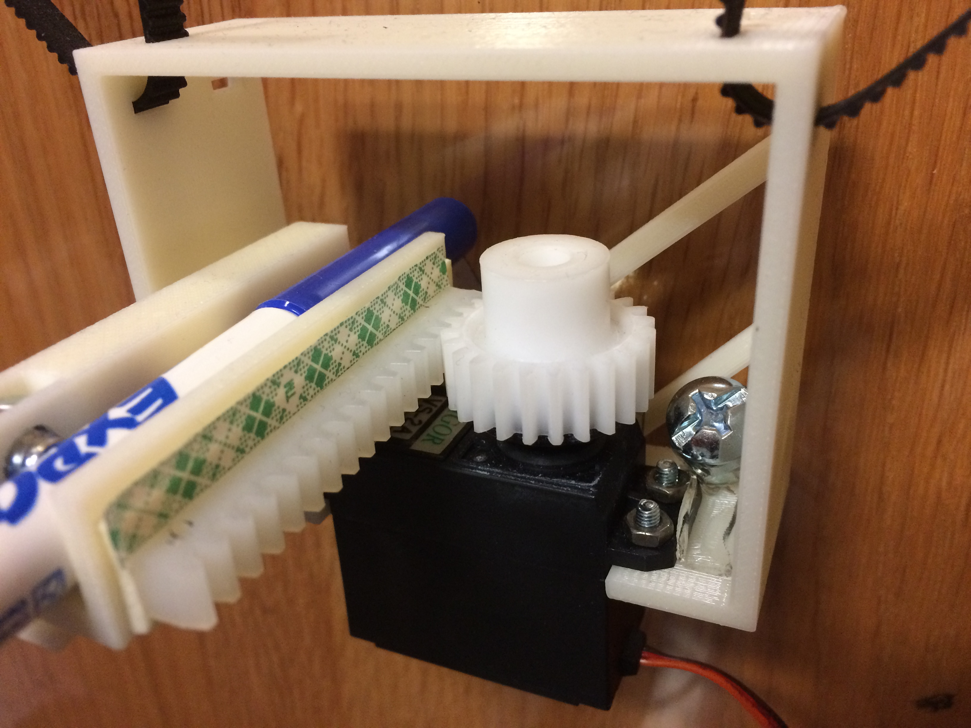
I 3D-printed a pen holder, which uses a small servo to lift and press a pen.
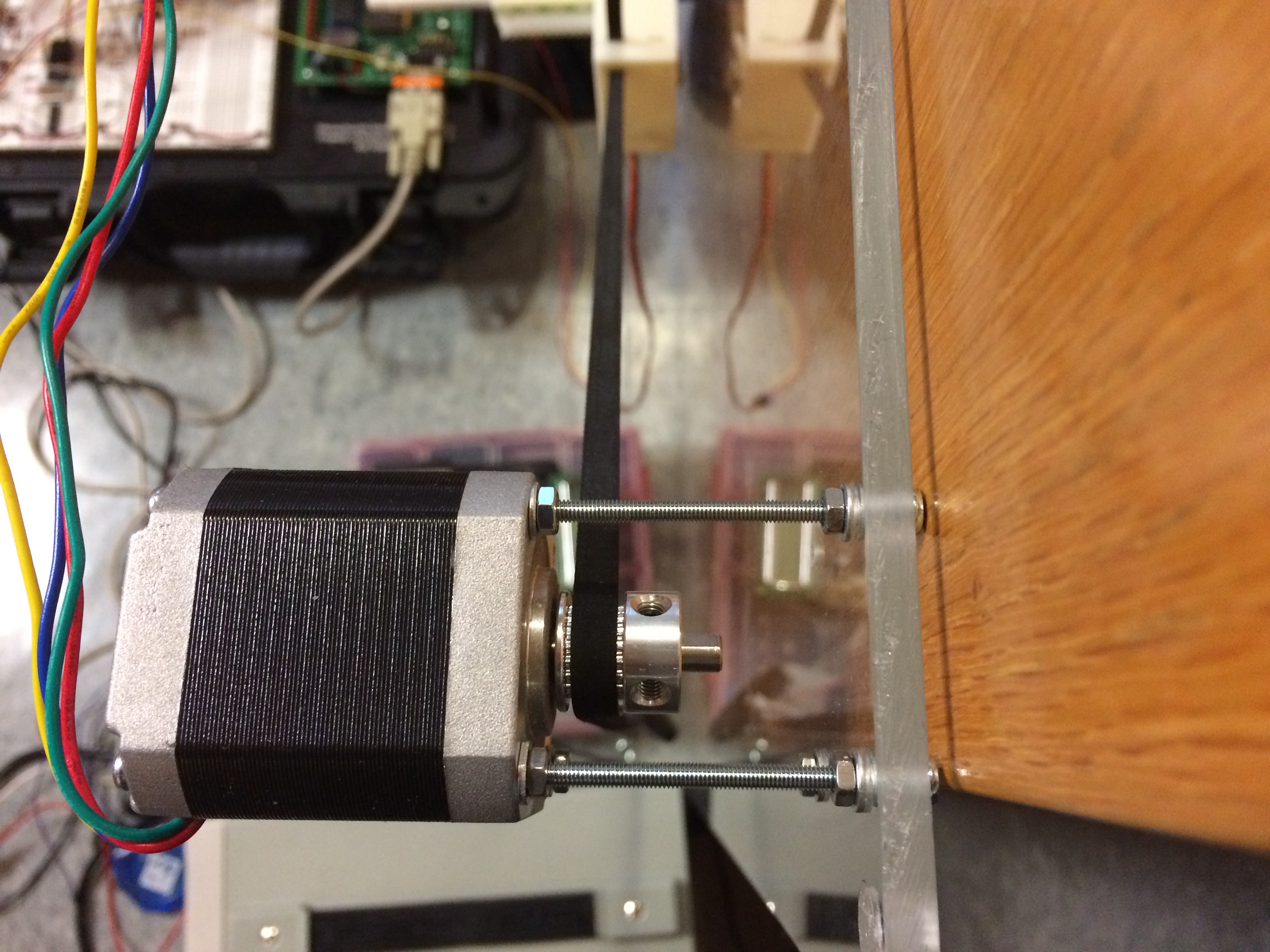
The NEMA 17 stepper motors are mounted directly on the acrylic sheet. I thought about mounting them on suction cups so that I could stick them to any window or whiteboard (inspired by this cool wall plotter), but I decided to keep it simple for the scope of the class project.
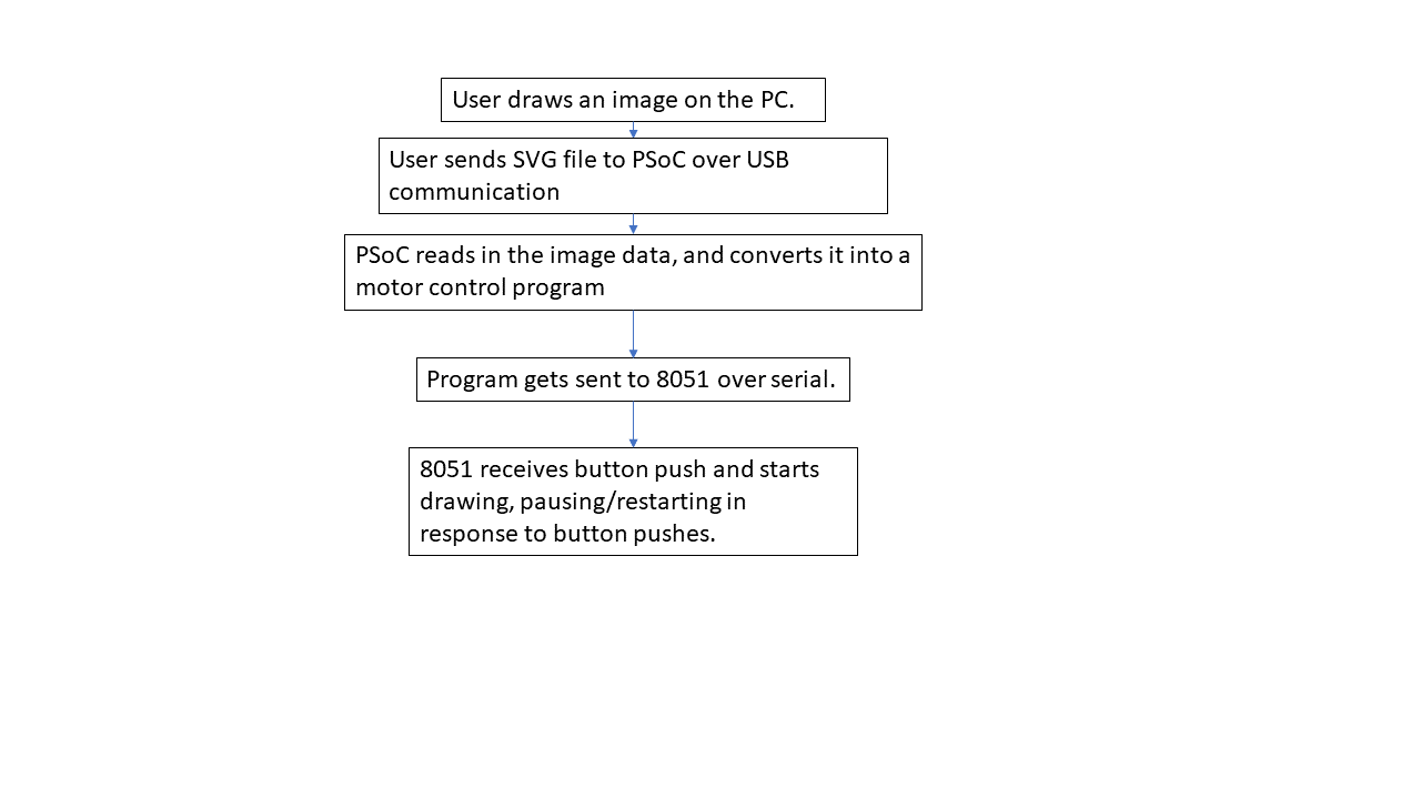
The user can run a script to send a flattened svg file to the PSoC. The PSoC then converts the lines into motor steps and directs the 8051 to control the stepper motors and the servo, through stepper motor drivers and an 8254 timer/counter chip. A couple charts of the software/electrical flow aare below.
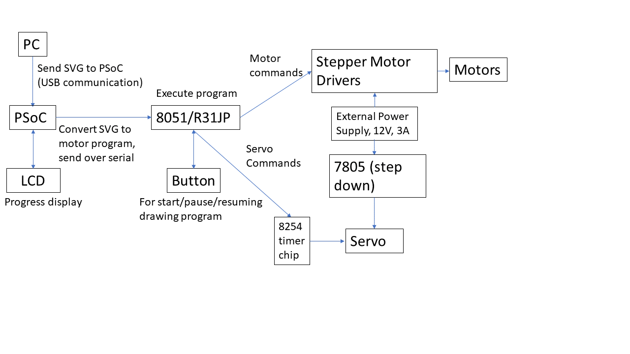
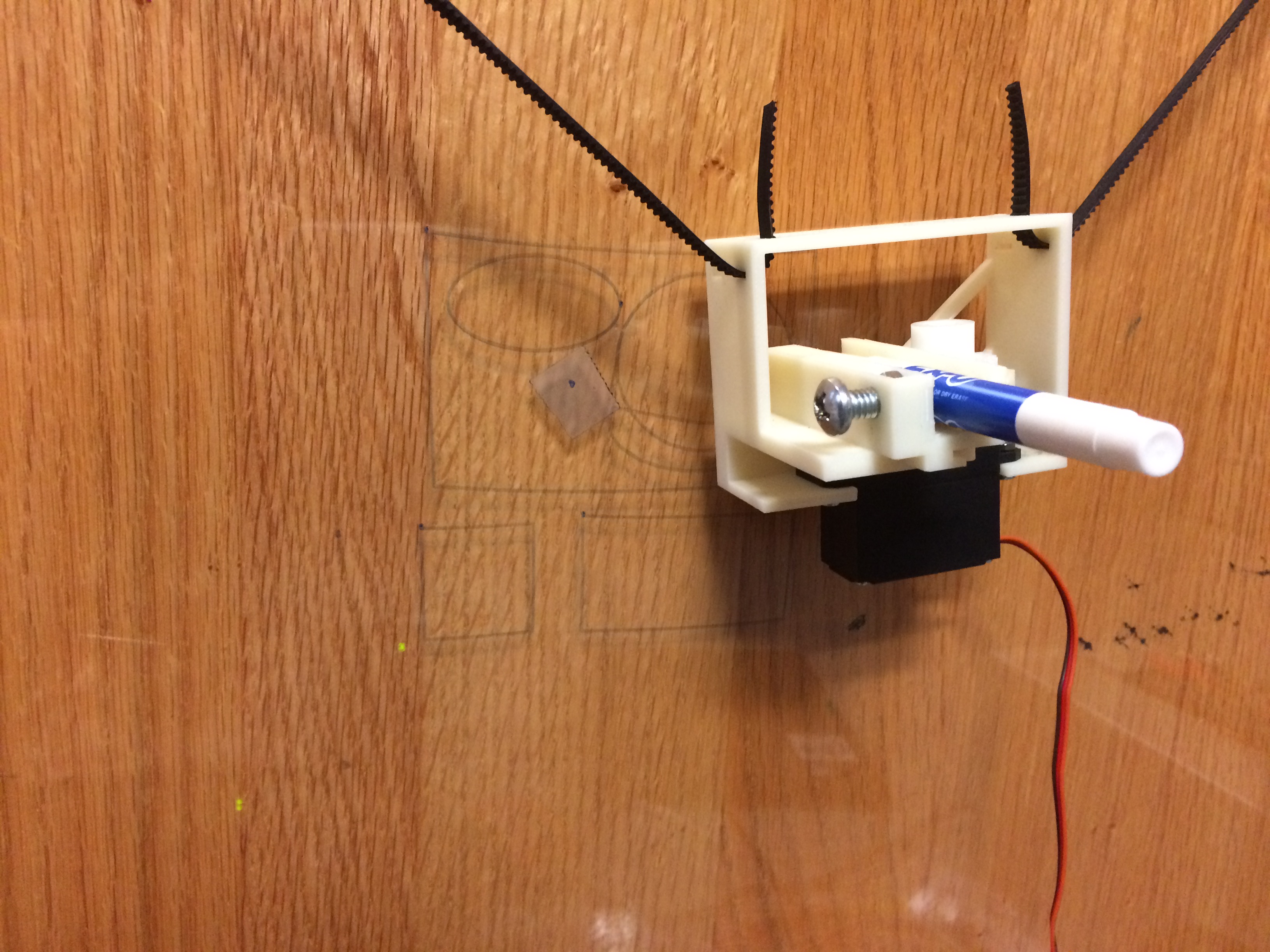
A full view of the plotter, including the huge R31JP Lab Kit (which houses the 8051 and other electronics we used for the class) on the left, and the PSoC in the center.
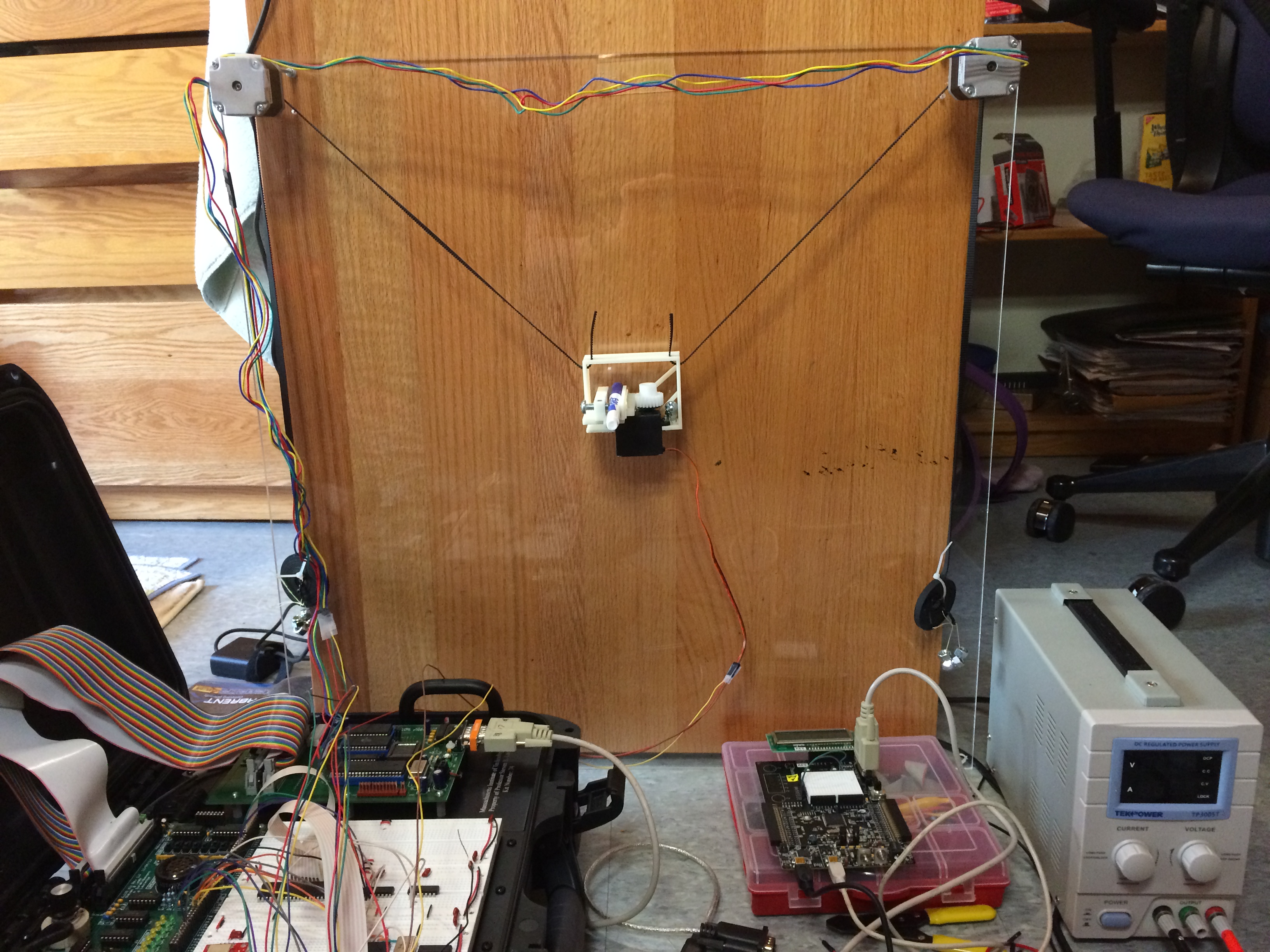
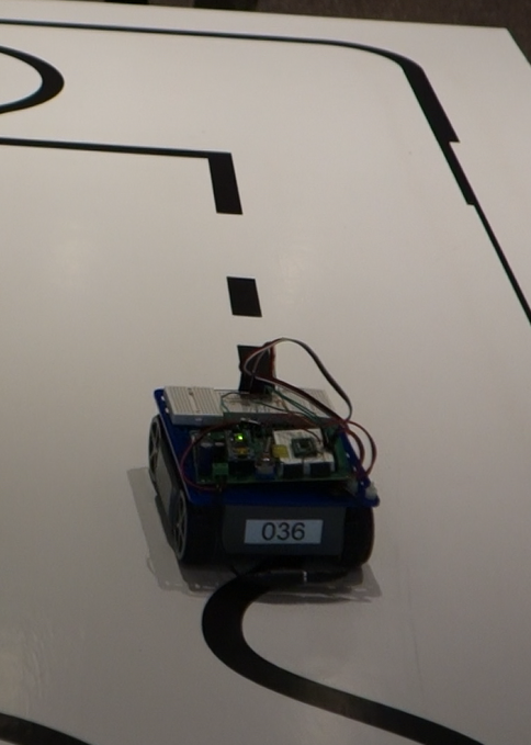
The plotter after drawing some polygons.
Some sites/other V-plotters that inspired this project:
https://tinkerlog.com/2011/09/02/der-kritzler/
http://www.homofaciens.de/technics-machines-v-plotter_en.htm
http://www.instructables.com/id/Polargraph-Drawing-Machine/
Things I would have improved if I had more time:
-speed/heatsinking: if I stepped the motors too quickly, the drivers tended to overheat since I did not have proper heatsinks for them. I could have put a fan over them, also.
-scalability: putting the motors on suction cups or hooks to stick onto any wall or window would have been awesome.
-pen carriage stability: extending/retracting the pen and rapid movement caused the pen carriage to wobble a little. I think I could have reduced the wobble by adjusting how and where the timing belts were attached relative to the pen and servo motor/COG, to allow for faster drawing and cleaner lines.
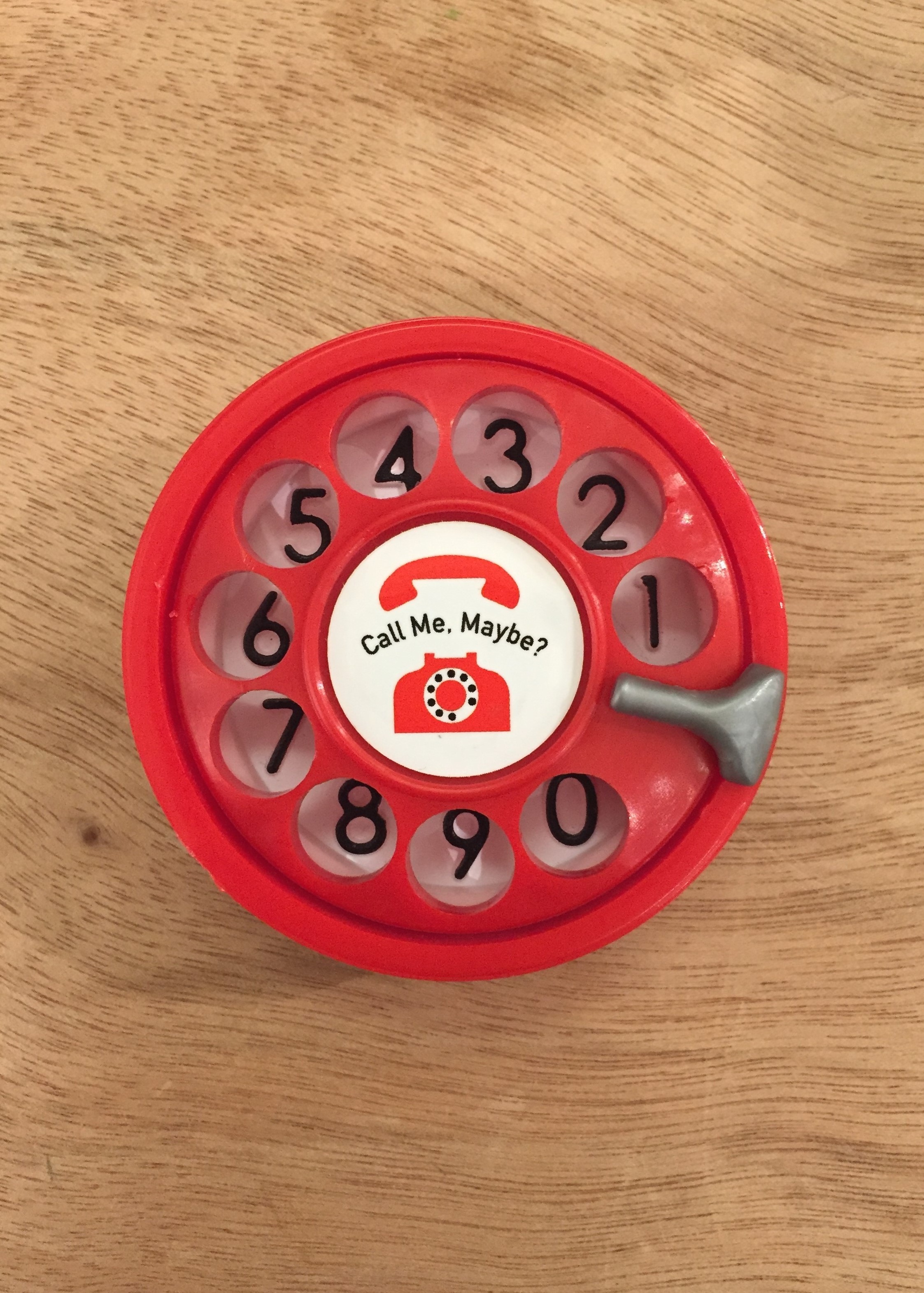
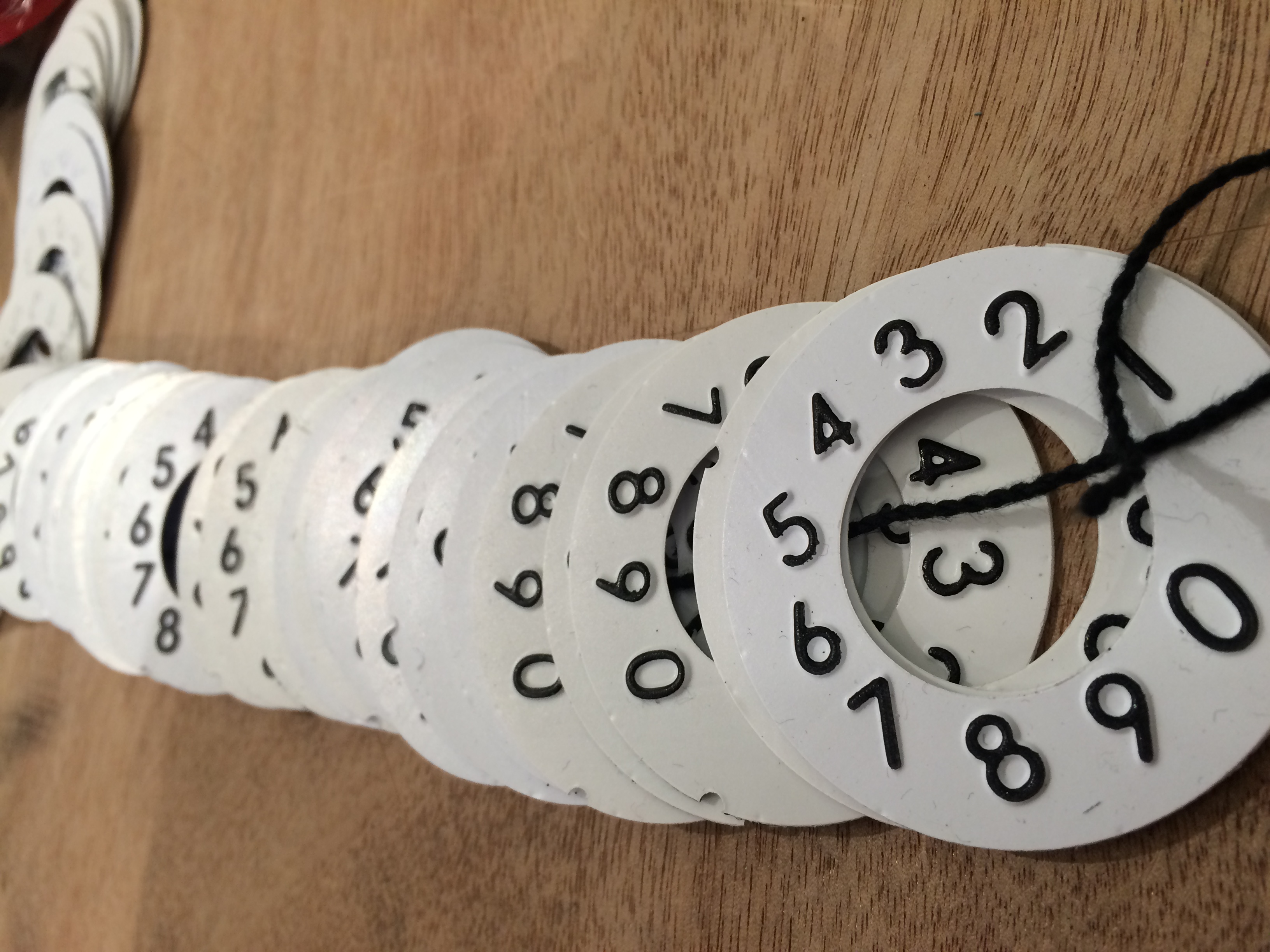
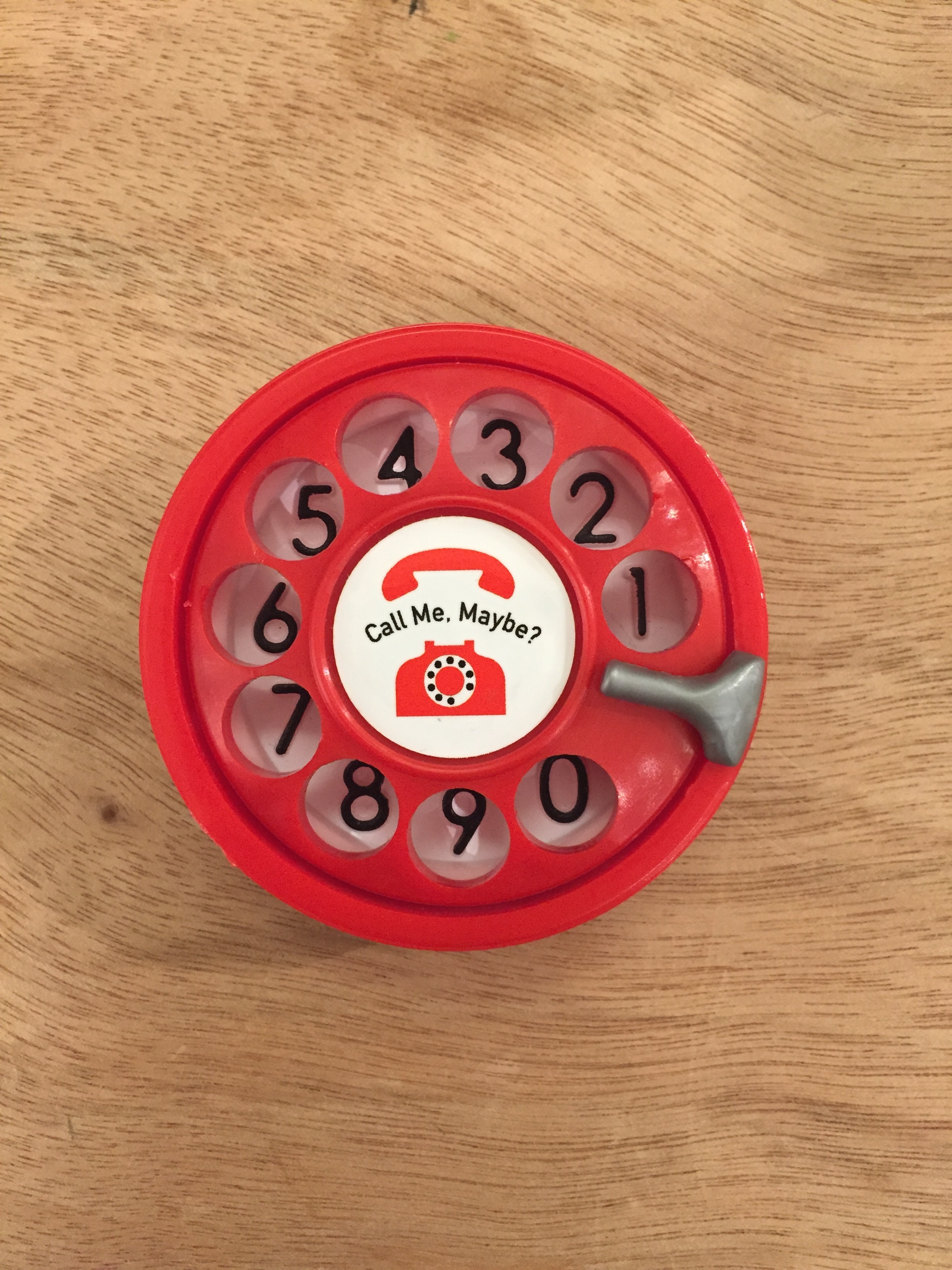
Rotary-Phone Themed Yoyo
I worked on a team of undergrads to manufacture 50 yo-yos! Our theme was a rotary phone. Our team blog is here: http://callme2008.blogspot.com/
Our final product being used:
The numbers don't line up with the holes in the video since we yoyo-ed it too hard and broke the end stop.
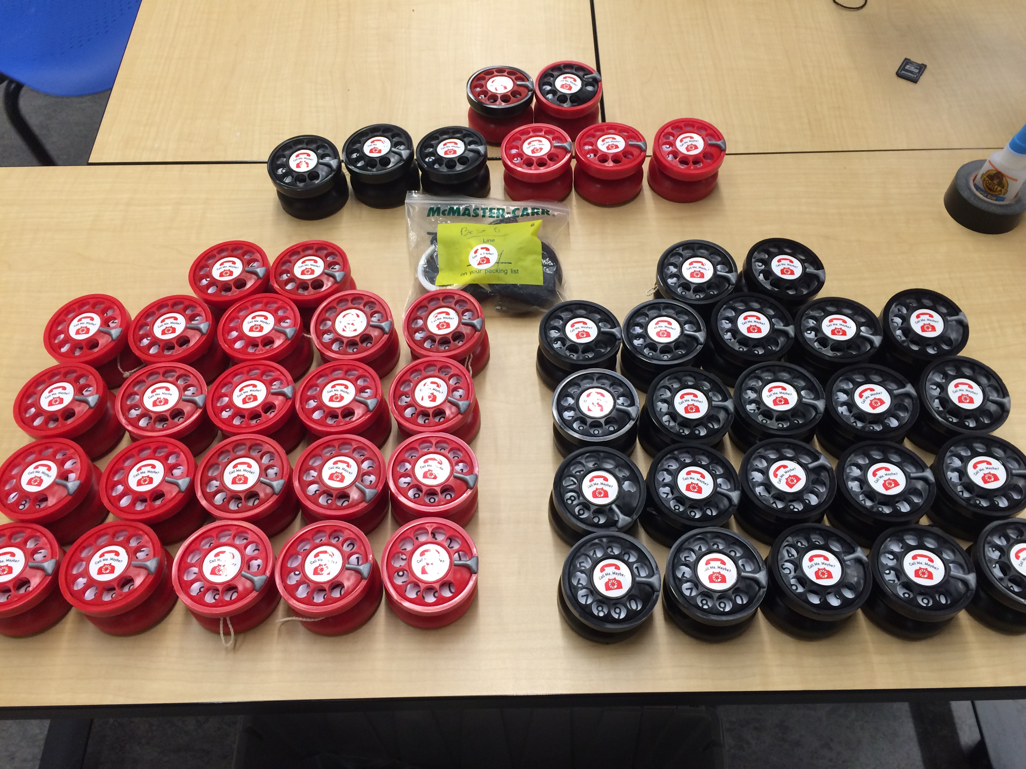
Each half of our yoyo consisted of a base, rotary dial, fingerstop, retaining ring (all injection-molded), and a number pad (thermoformed).
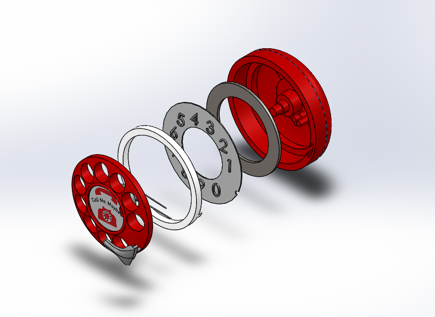
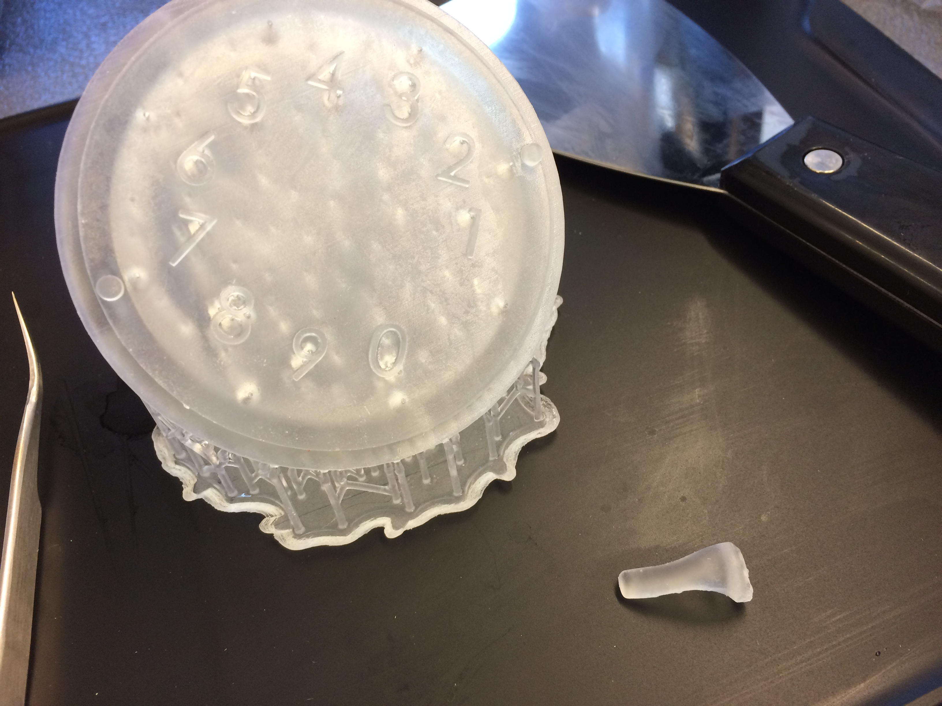
I worked specifically on thermoforming the number pad. First, I 3D-printed a mold using the Form 2 SLA printers. (The little piece on the side was a prototype of the fingerstop, which I helped do some CAM for.)
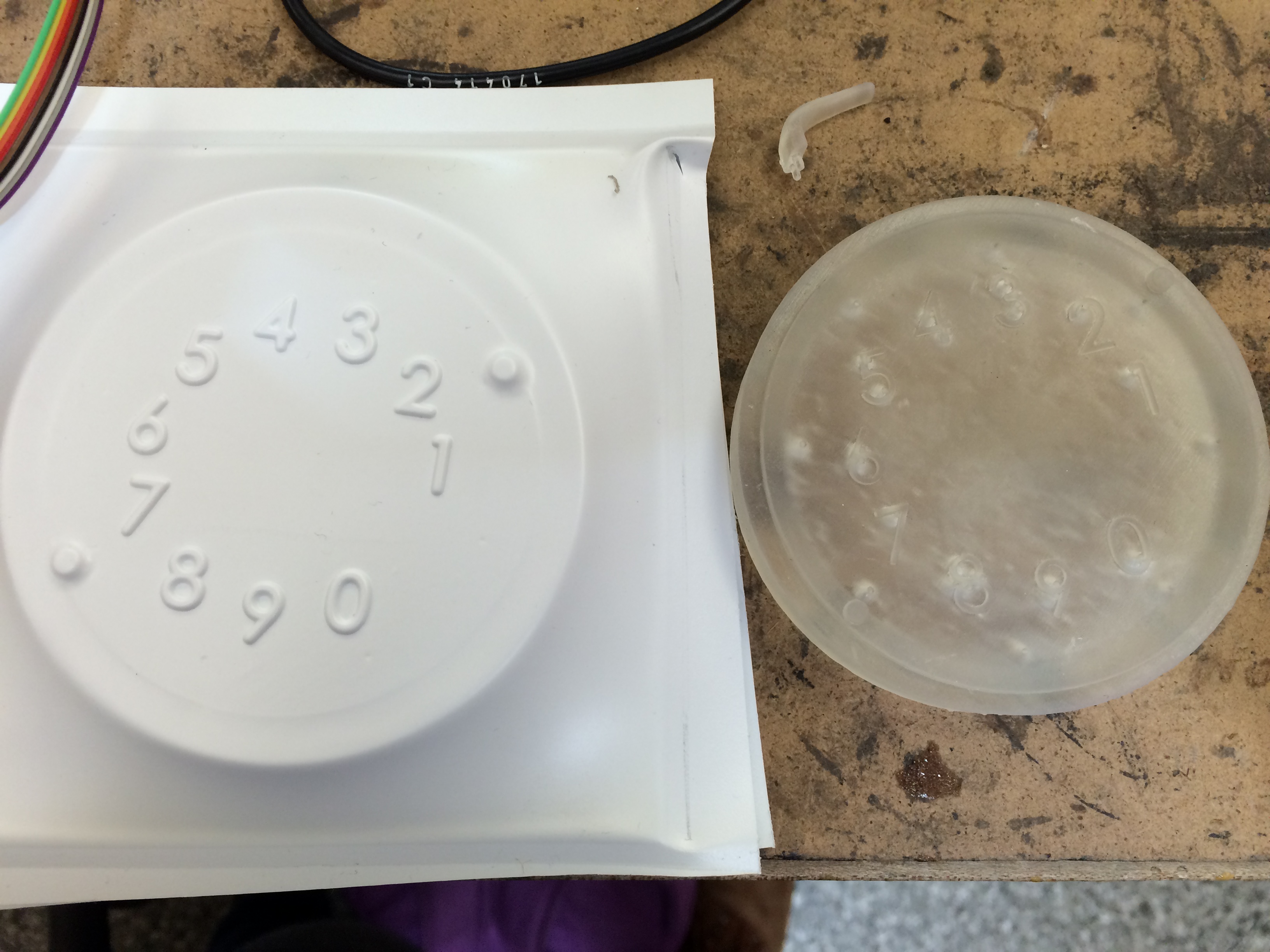
Then, some test thermoforming, to figure out what the best times were for heating, forming, and cooling.
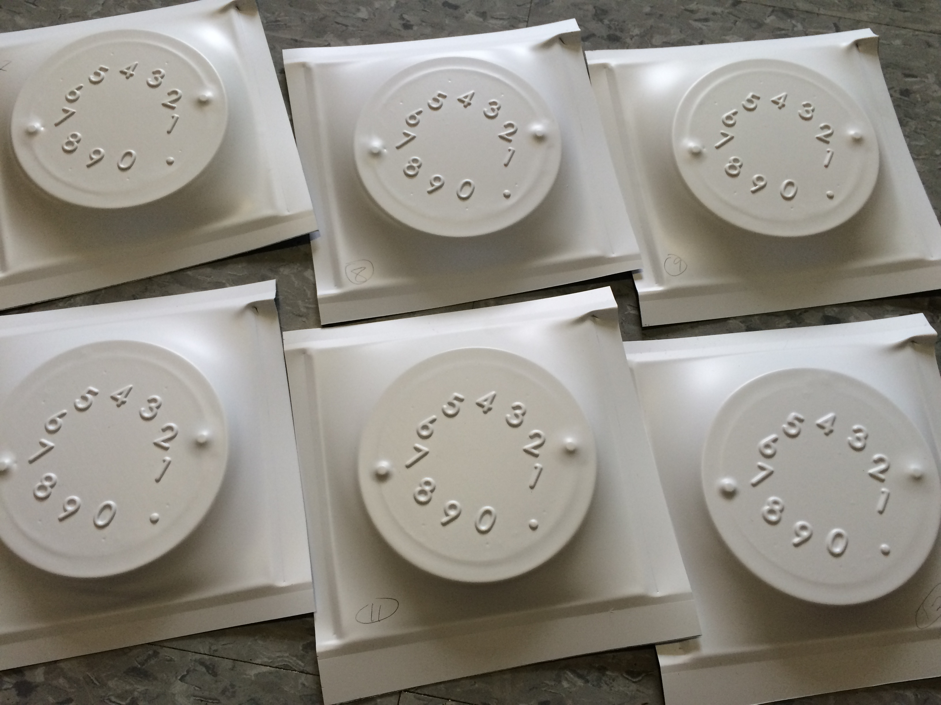
Punched and painted the raised numbers using a roller and acrylic paint + stencil
The finished yoyo!
And a cool special yoyo, from when we were transitioning colors in the injection molding machine.
 Back to portfolio
Rollercoaster
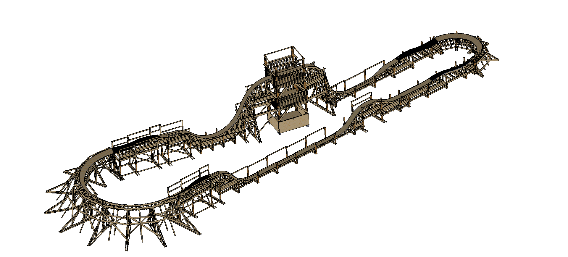
Designed, built, and operated a rollercoaster for freshman orientation 2017, except the rollercoaster we designed was different from the one we actually built.
Previous years had straight-track rollercoasters, where the track was straight and ony went up and down. Initially we wanted to try something new and introduce banked turns, for a fully closed loop track.
A CAD screenshot of the designed rollercoaster with banked turns:
I worked mostly on the cart for the rollercoaster. It was to be a welded steel frame.
The cart in its latest iteration, though still with a few unresolved issues:
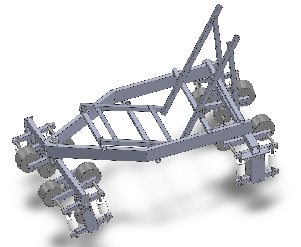
How the cart was meant to sit on the track banked turn:

In the end, we decided that it wasn't a good idea to go forward with the banked-turn design, largely because:
1-It was significantly larger/longer than previous designs, and we were unsure if we could build it in time.
2-Because the cart had so many degrees of freedom, it seemed beyond our skill/ability to predict all of its potential failure modes.
3-The cart design still had unresolved issues when it was time to submit our designs for final review
4-We could not determine how we were going to test the rollercoaster for safety conclusively before we determined that it would be safe for human use (similar to #2)
5-We really wanted to make something that would work, and we thought the freshmen would probably be more excited with a straight-track rollercoaster that worked than a turning rollercoaster that might not work.
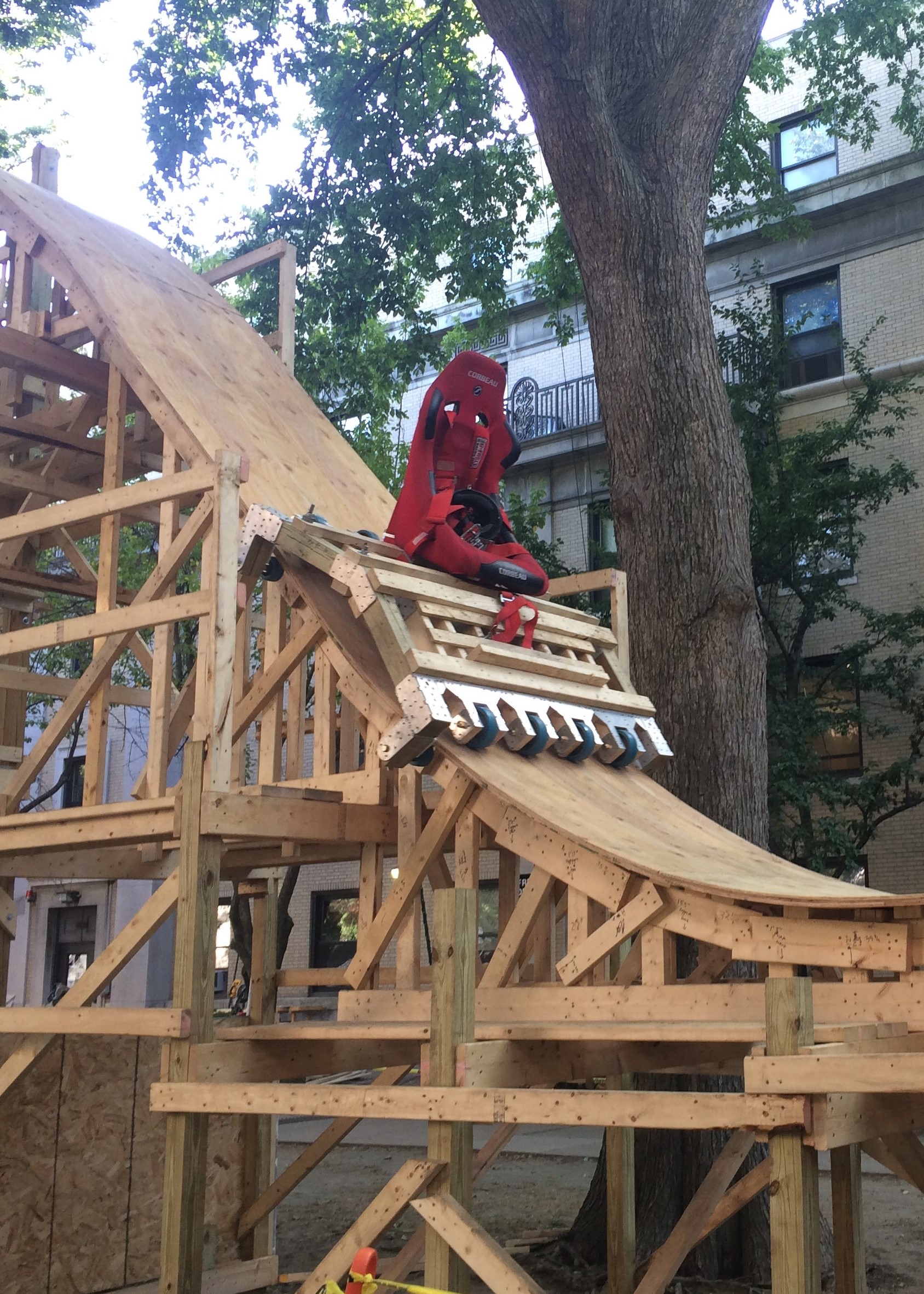
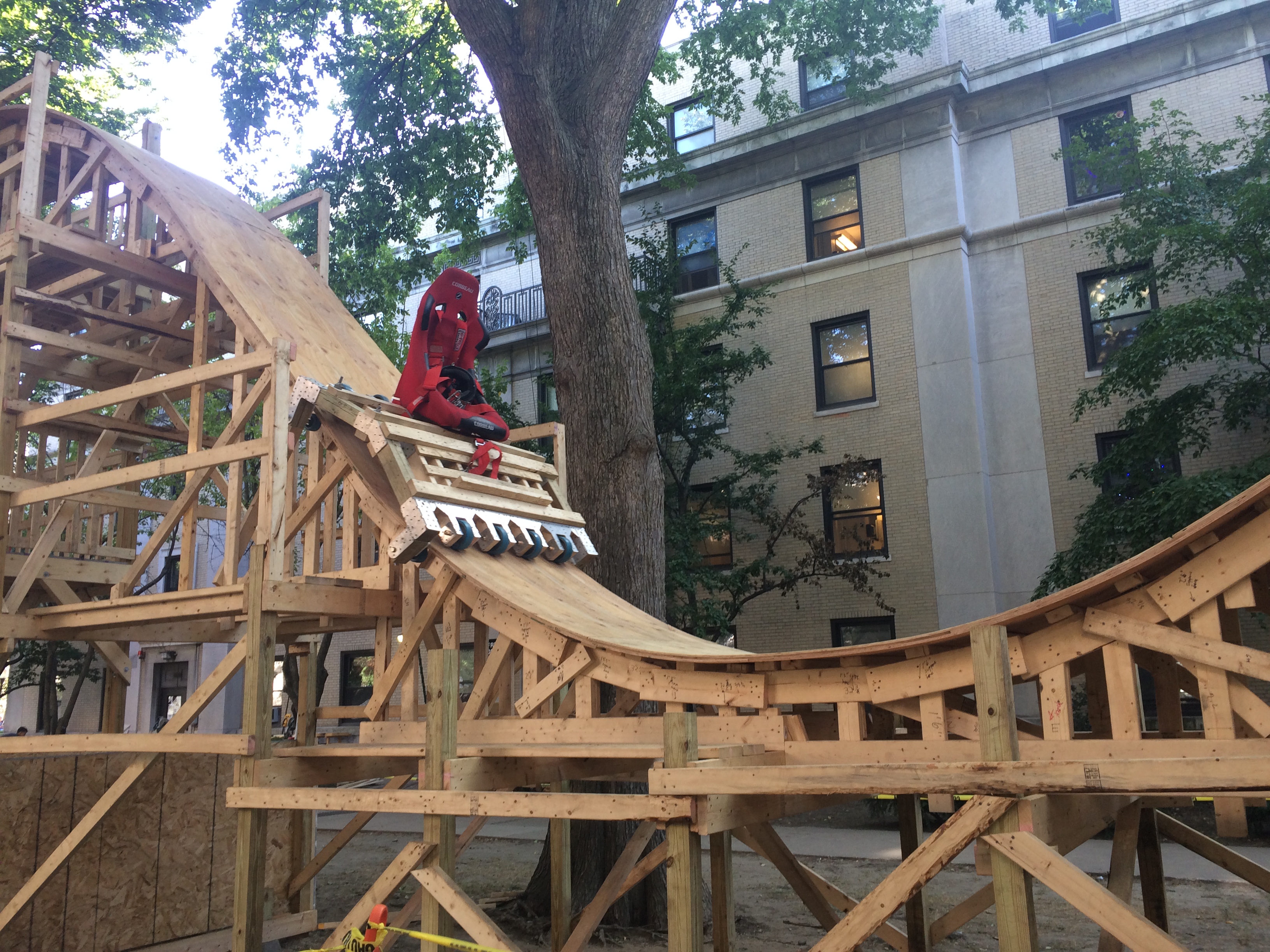
With permission from the original designers (Wesley Lau, Ben Katz, Jaguar Kristeller), we ended up building a previous years' straight-track rollercoaster (+cart!) design.
The cart looked like this:
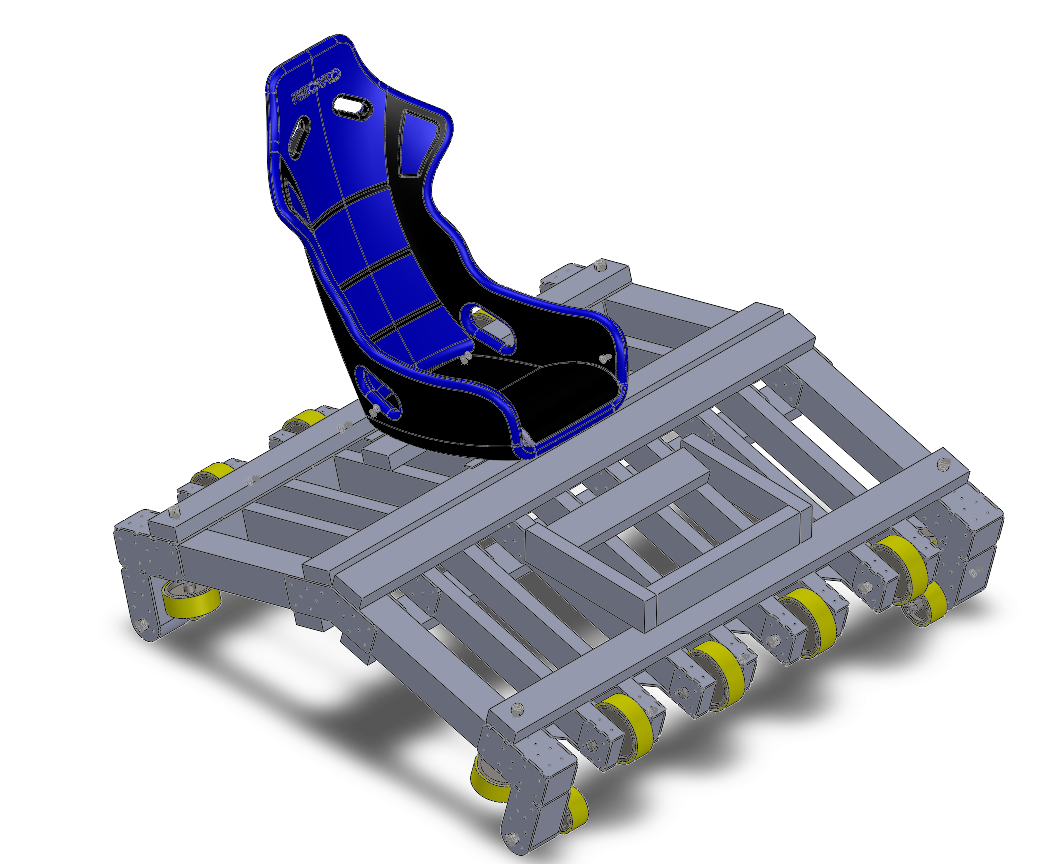
During testing, we found out that the side wheels were not aligning well with the track, so we swapped them out with delrin skids. We bolted the 5-point harness directly to the wood cart body.
Cart on the track during a test dry run:
More photos:
Evening construction cleanup:
Me doing cart maintenance, pc: Elizabeth Chang-Davidson.
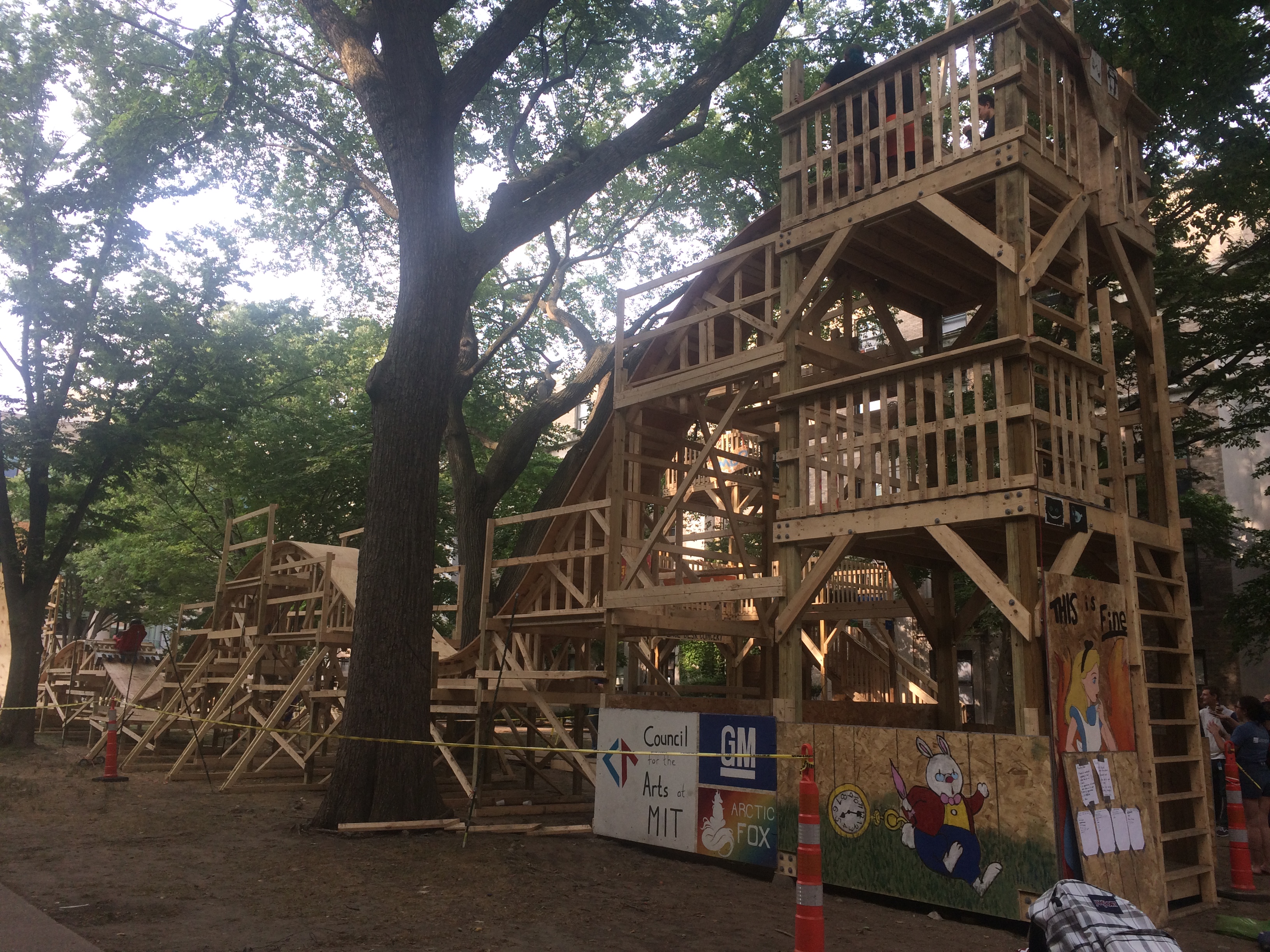
Panoramic of the mostly-finished coaster, pc: Elizabeth Chang-Davidson.
Mid-construction, pc: Elizabeth Chang-Davidson.
Cart construction, pc: Elizabeth Chang-Davidson.
 Back to portfolio
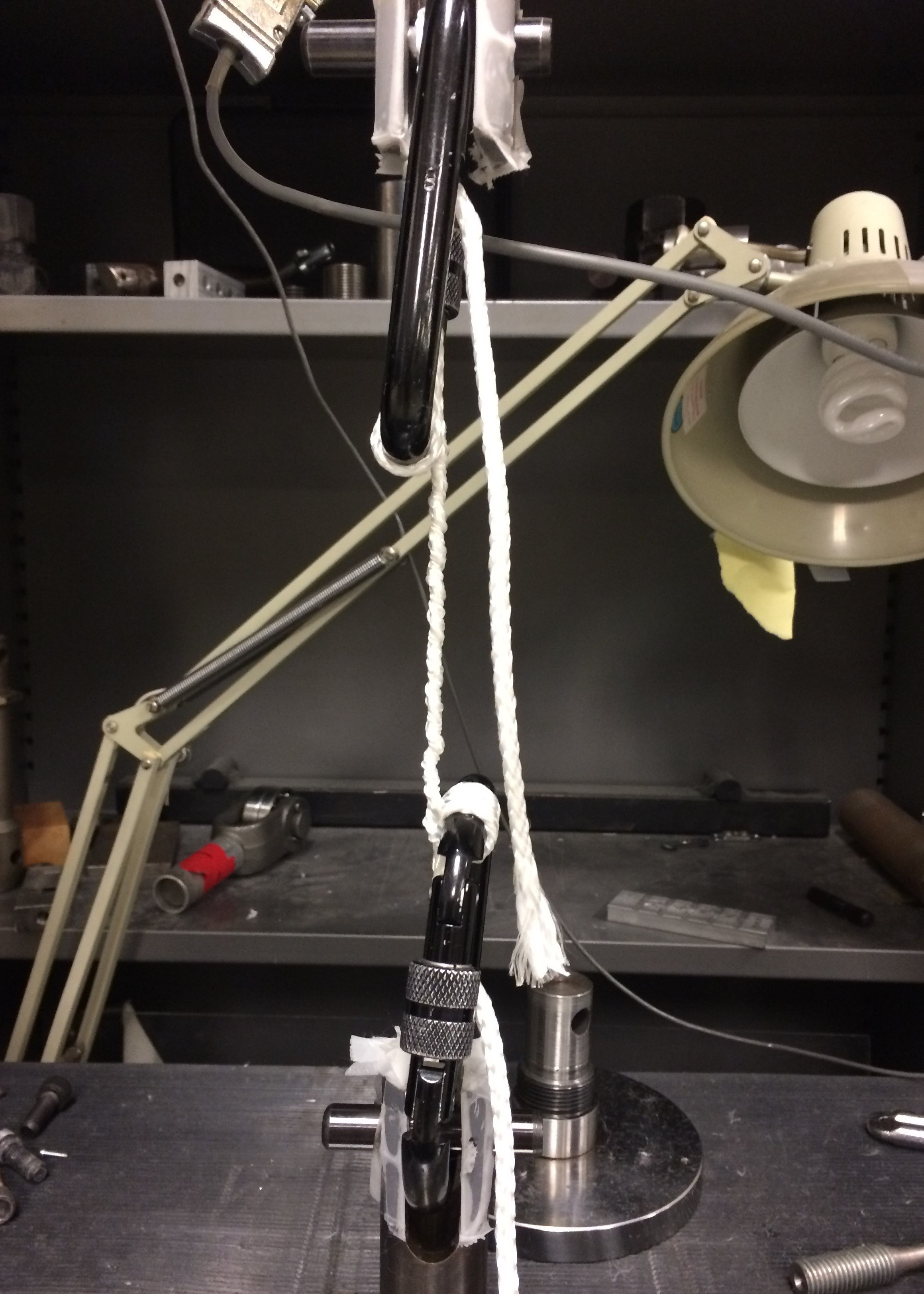
Rope Tensile Testing
Tested and quantified the tensile strength and elastic modulus of 3/16" diamond-braided nylon rope. This project was done for a measurement and instrumentation course (2.671), where students were asked to choose some quantity to measure.
Using an Instron machine, I tensile tested ropes to failure. Below are my final presentation, paper, and poster for the course.
Poster:
Paper:
Presentation:
Back to portfolioRemote-controlled robot
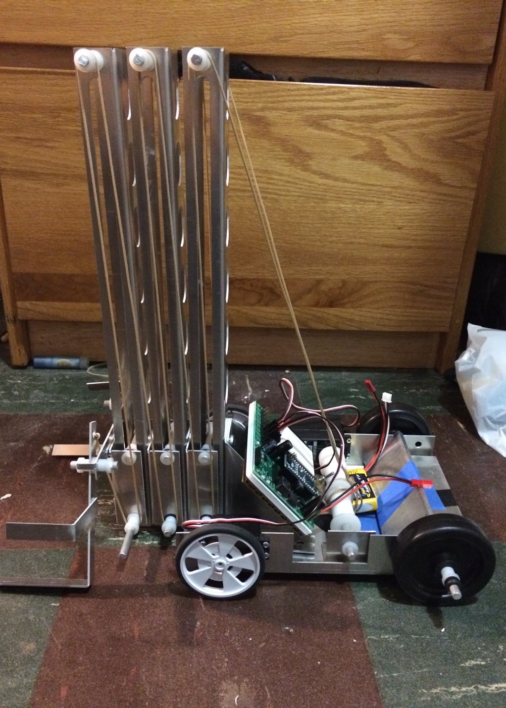
I designed and fabricated an RC robot that lifts two lanterns and hangs them on a hook about three feet above ground level as part of 2.007, MIT's introduction to design and manufacturing class (often known as the root of FIRST robotics). This robot won the Whitelaw Prize for Originality in Design and qualified for the final tournament with the top 32 scoring robots in a class of 150 students.
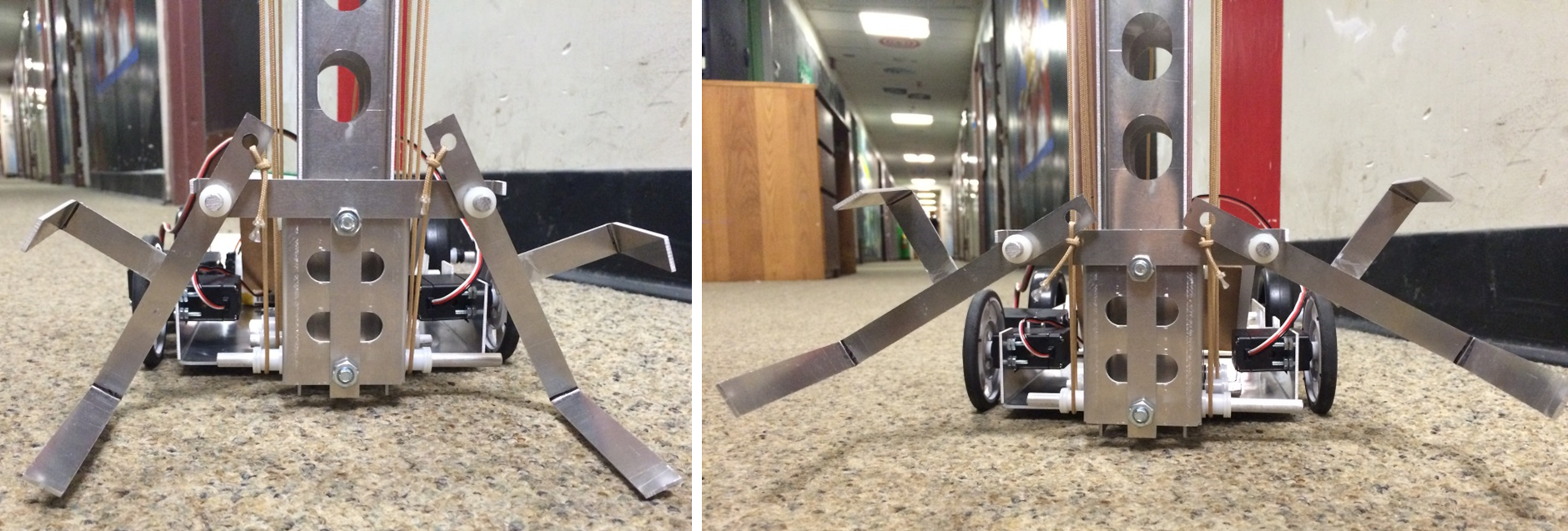
The task breaks up into two parts: (1) lifting the lanterns and (2) rotating the lanterns such that both of them can hang from the hook at once. To make operation easy and keep everything as simple as possible, I tried to do complete both of these tasks with only one motor. Here's a video of operation (watch all the way until the end to see the rotation!)
Some of the constraints that I worked with included a maximum robot size of 16"x16"x16", a time limit of 1.5 minutes, and a specific set of servos/motors for actuation.
I started off the design process by brainstorming methods of lifting. Feasible options I considered included a scissorlift, multi-stage arms, and a linear lift. Prior class knowledge informed me that scissorlifts were particularly difficult to make stable and actuate effectively, and multi-stage arms seemed like they would involve too many orientation changes, I decided to go with a linear lift.
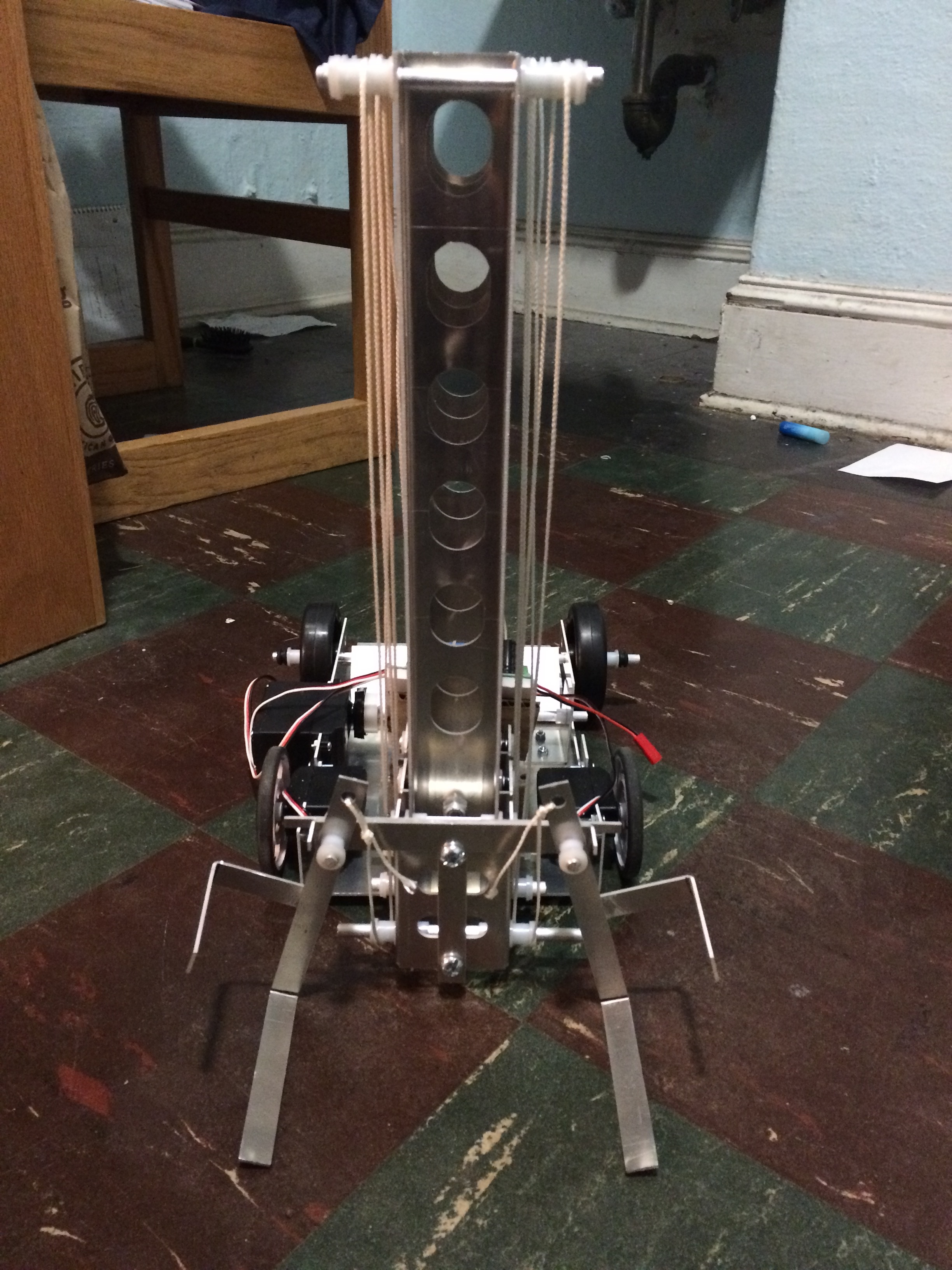
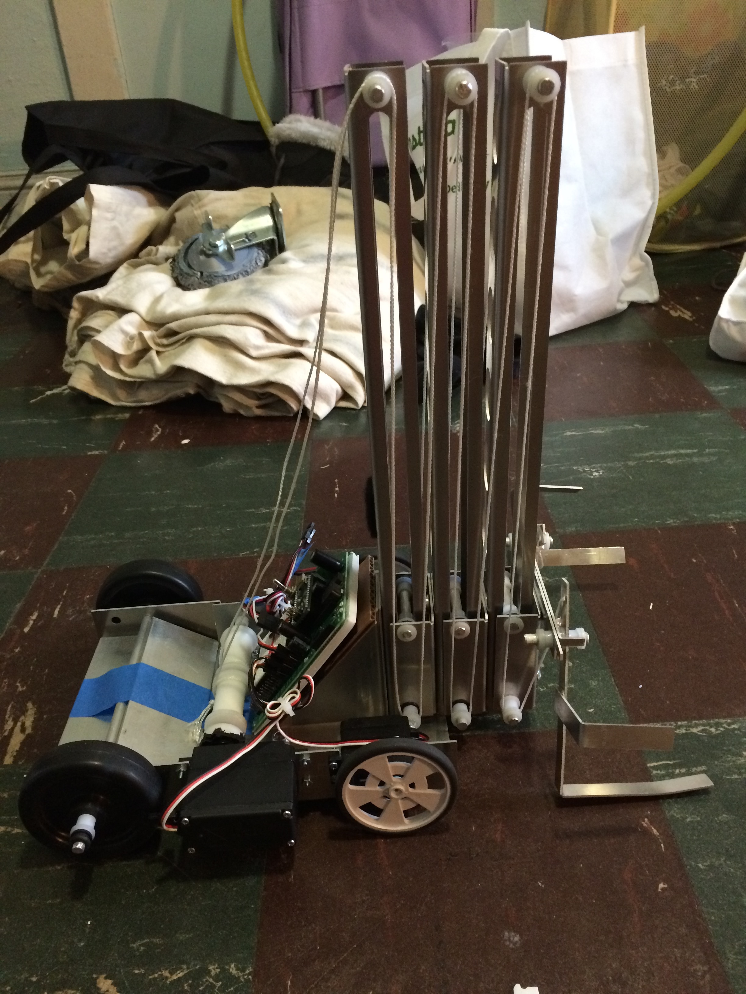
Some preliminary lift designs are below. Since I was having trouble weighing the benefits of more material/stability vs. minimizing machining time and weight, I CADed them out as a quick way of visualizing them with reasonable dimensions. The final lift design I decided to go with is on the right, after getting a feel for the stiffness and weight of the aluminum sheets.
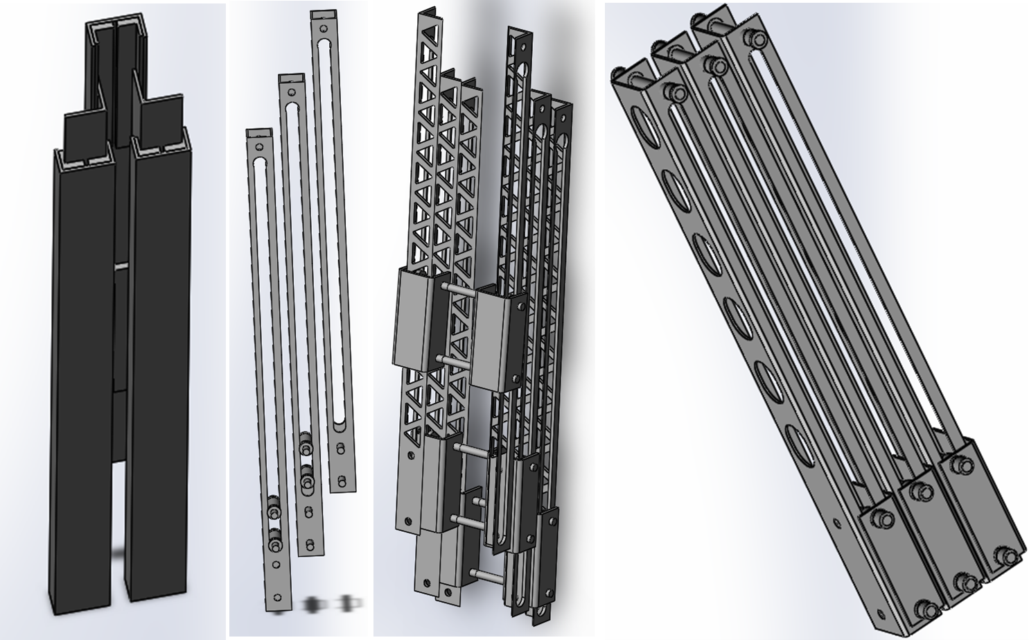
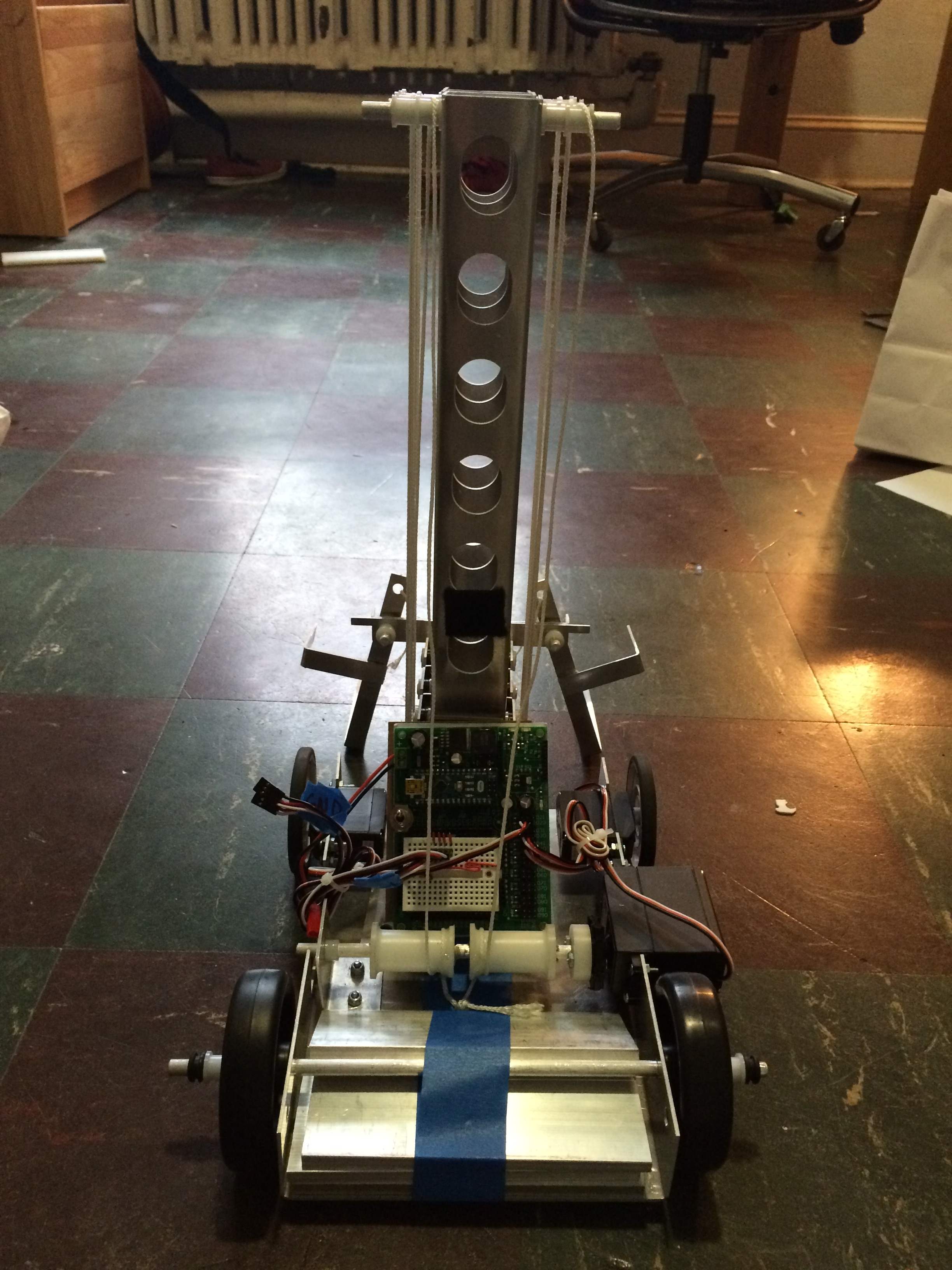
I made sure to reduce friction as much as possible by having no aluminum-aluminum rubbing interfaces, using bushings for the pulleys and interfaces between each lift stage. This also turned out to be a good way of constraining the lifts horizontally relative to each other, since each bushing has a small lip.
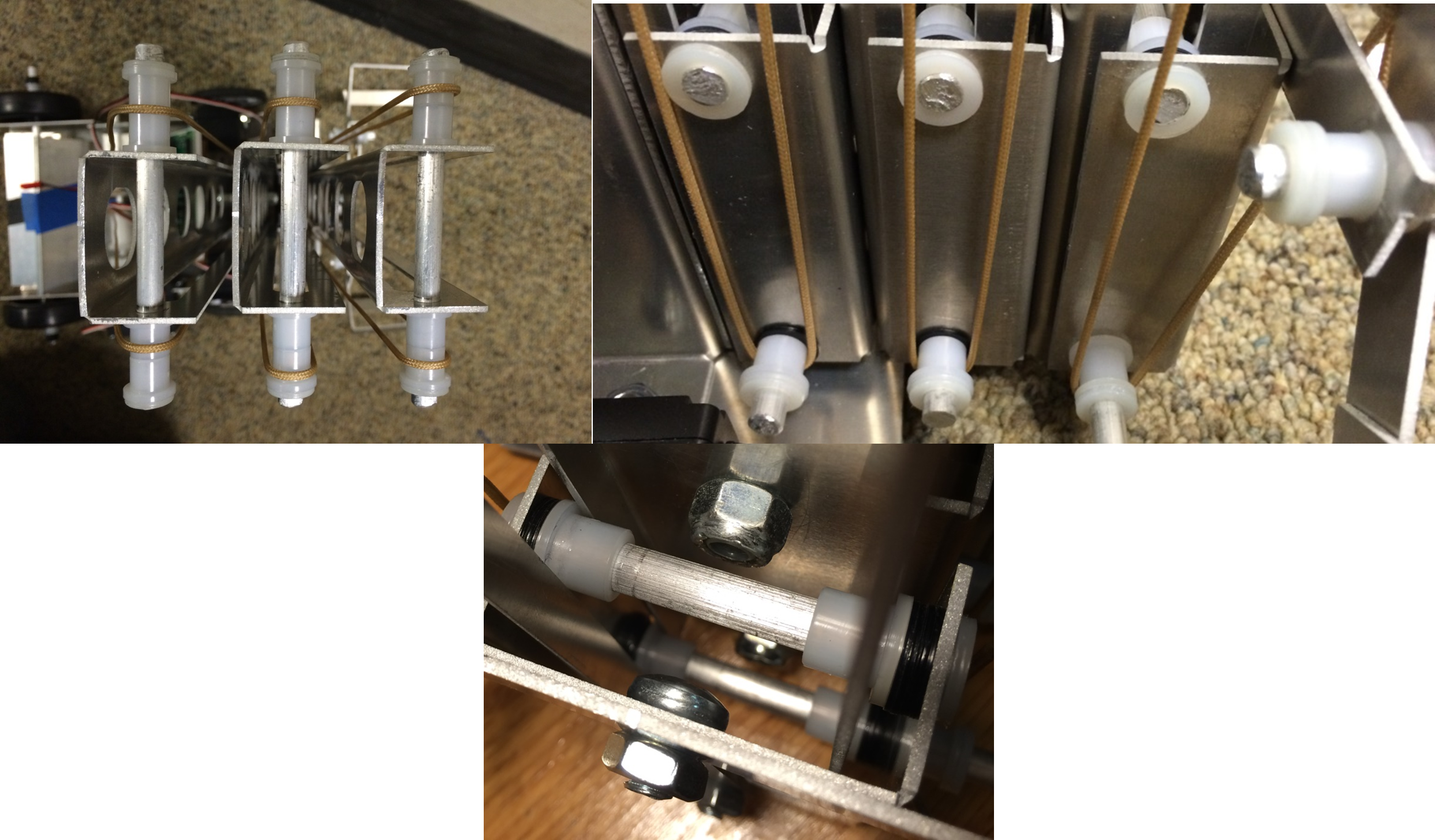
To rotate the two lanterns without requiring more actuation, I attached the ends of the pulley strings to arms that would rotate the lanterns in the appropriate radii (which I found by measuring the distances between the bottom outer corners of the lanterns in the desired start and end positions, and doing some sketches in Solidworks).
For the winch, I used a VS-11 servo motor (the highest power motor we had available to us), and delrin spools that I turned. I did a quick torque calculation to figure out the approximate highest efficiency radius. If I had time, I would probably go back and constrain the winch better, though--it was a little wobbly and probably could have gone faster.
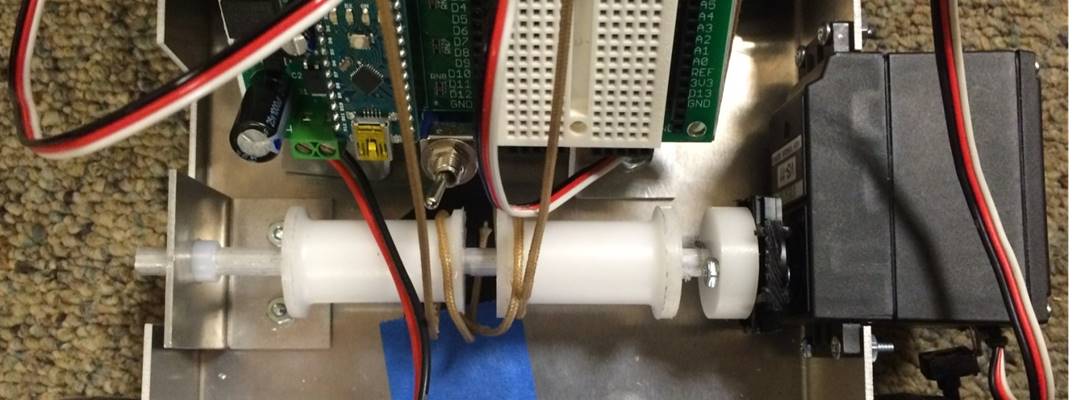
Fabrication-wise, almost all the pieces of my completed robot were made of waterjetted and folded sheet aluminum, or aluminum rods. I controlled it using a PS2 controller and an Arduino Nano. Some photos of the final robot are below.
 Back to portfolio
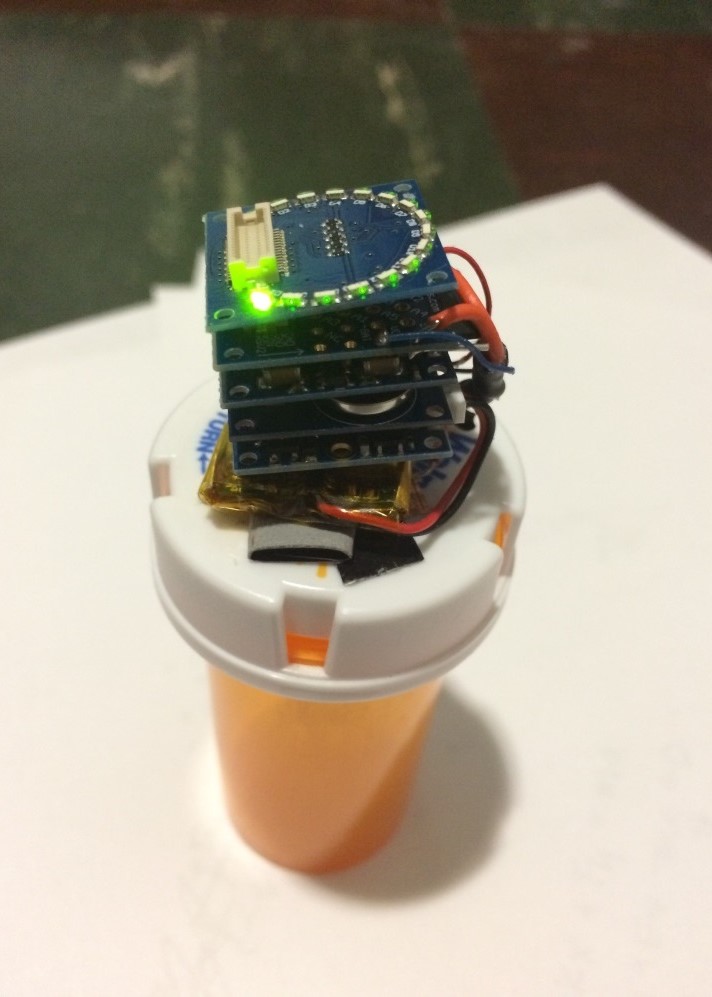
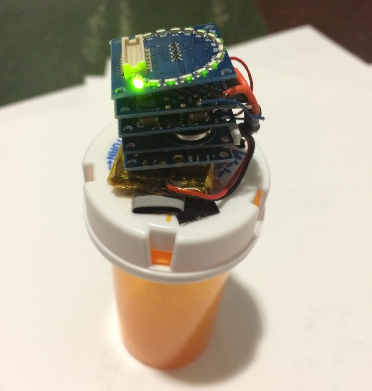
Smart Pill Bottle Construction Kit
I designed a “smart pill bottle” kit that modifies a standard pharmacy pill bottle as part of my work at Little Devices. The modified bottle tracks usage data whenever the bottle is opened and closed, and uses has an alarm to remind the user to take a dose at specified times. This kit is intended for use by caregivers and patients who require medication, and for use in educational/outreach contexts.
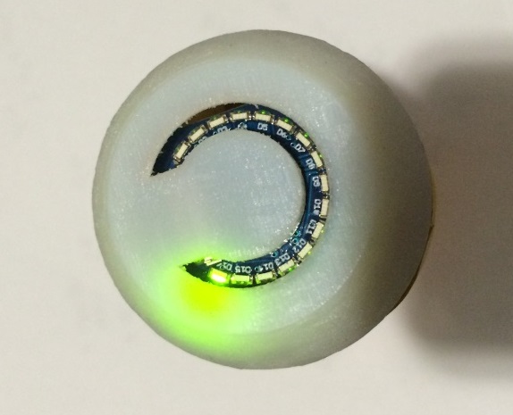
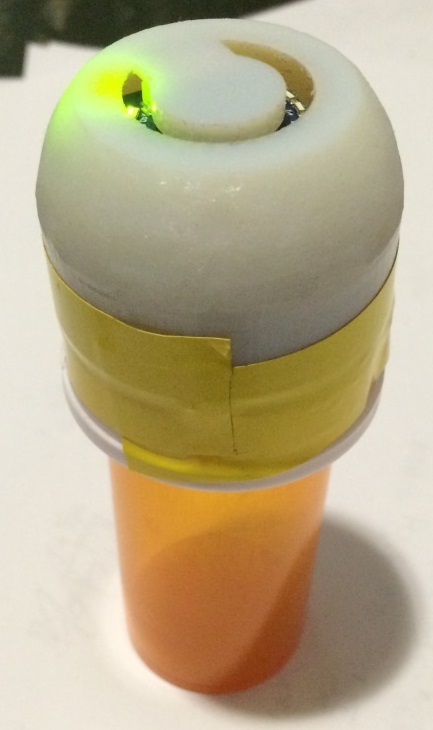
The bottle uses TinyCircuits, which are tiny modular Arduinos. There was already an existing code base for data logging, which I modified to add the alarm and usage sensing capabilities. To give it a completed look, I 3D-printed a cap to cover the circuits.
 Back to portfolio
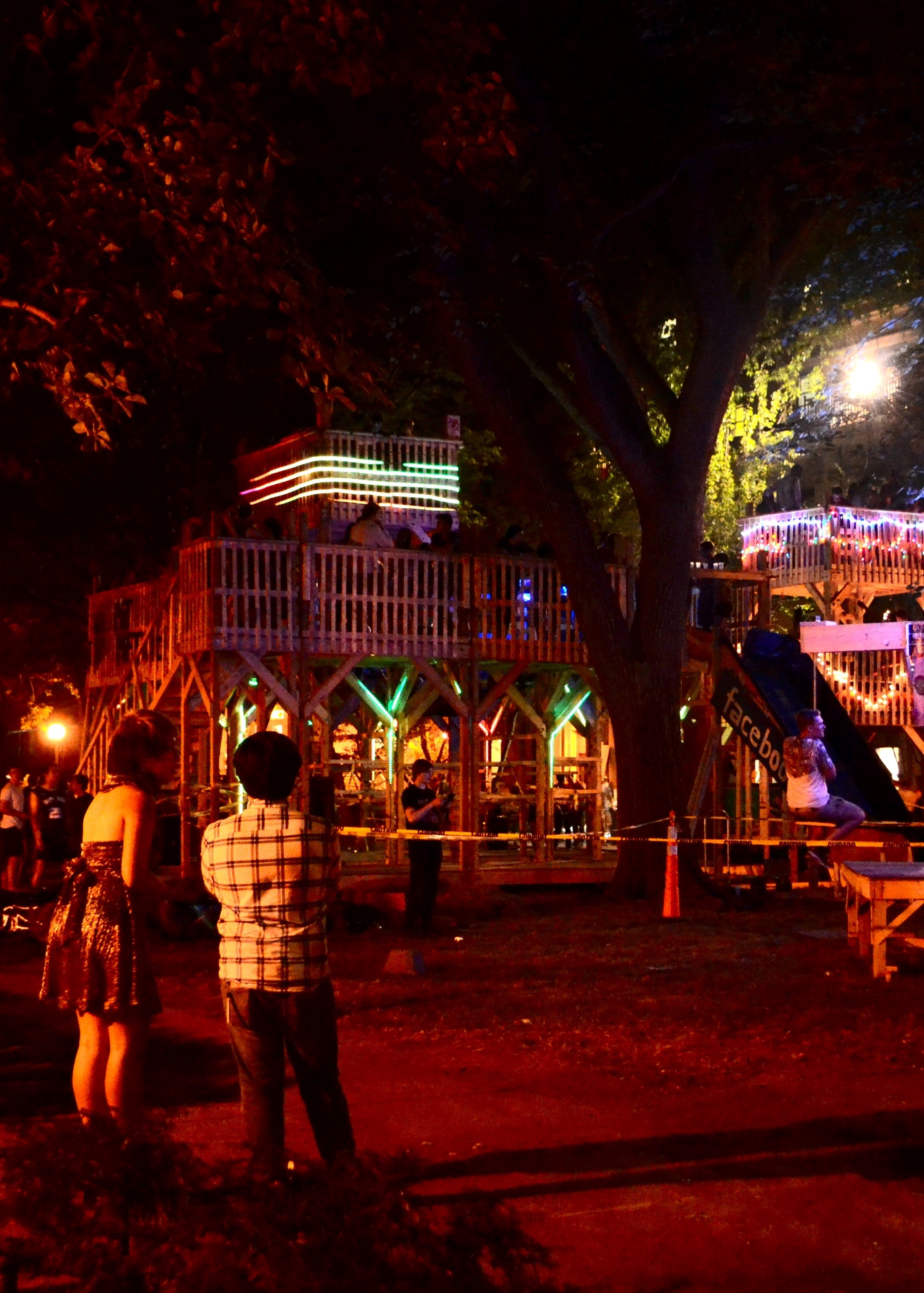
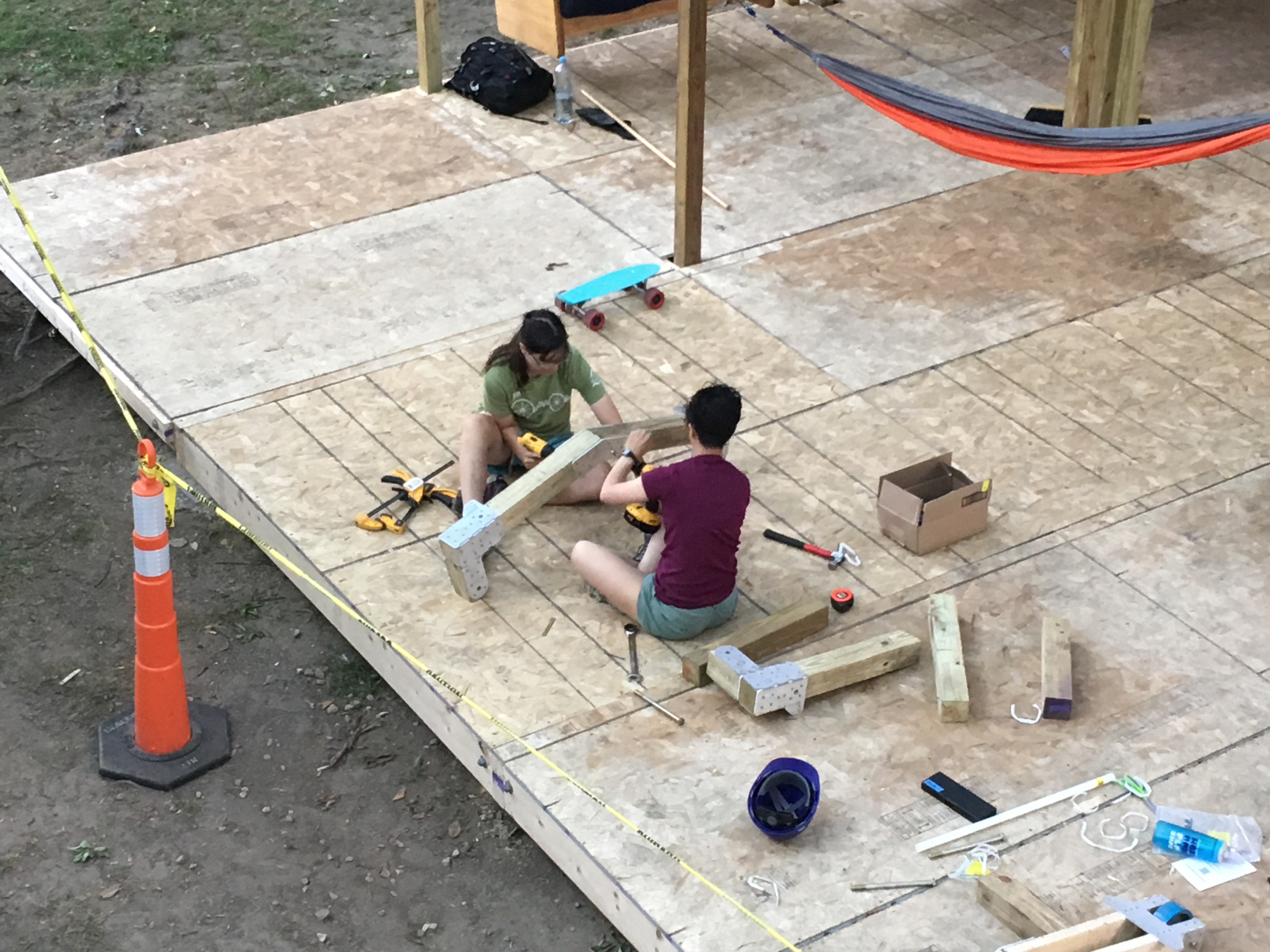
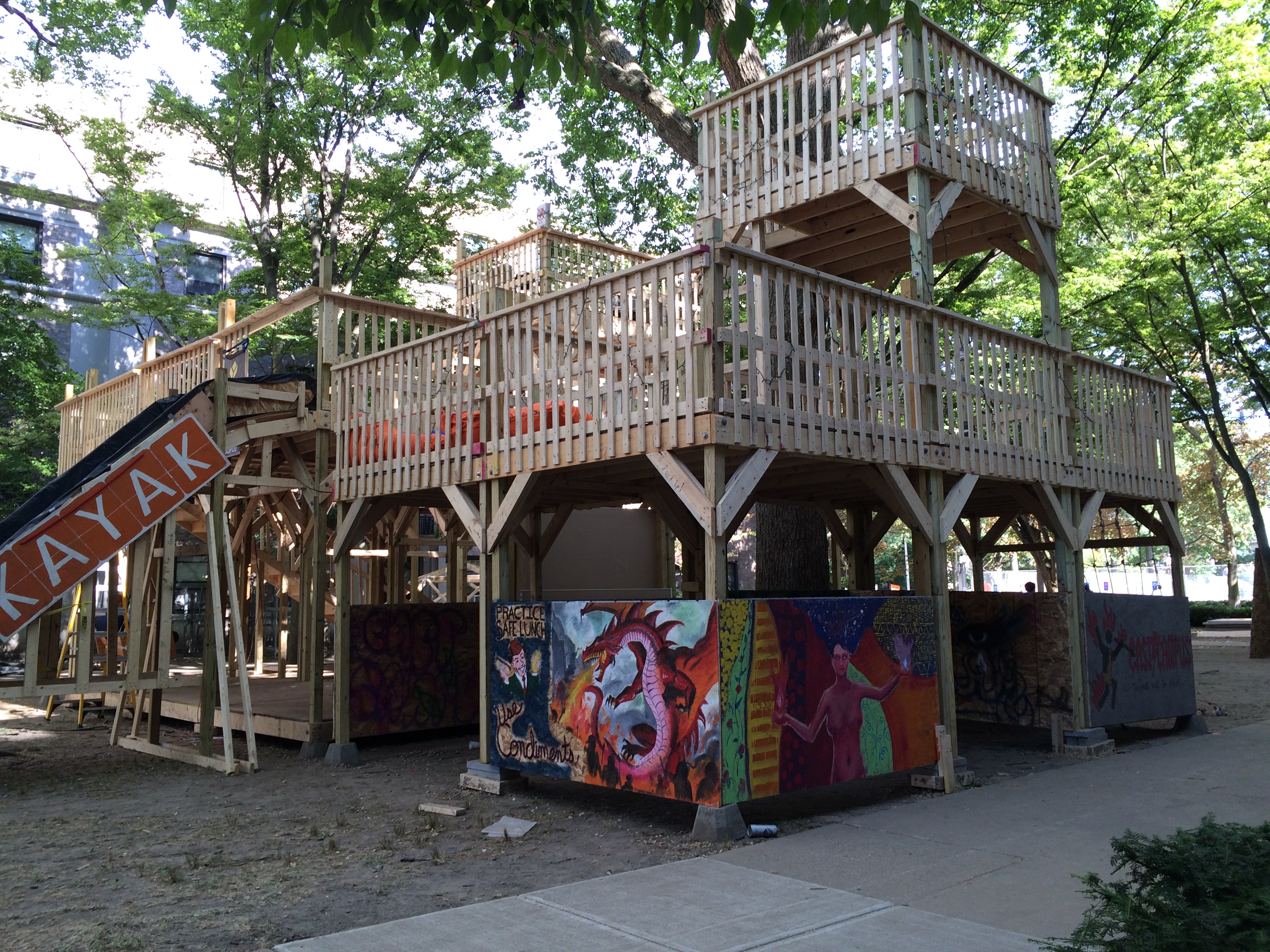
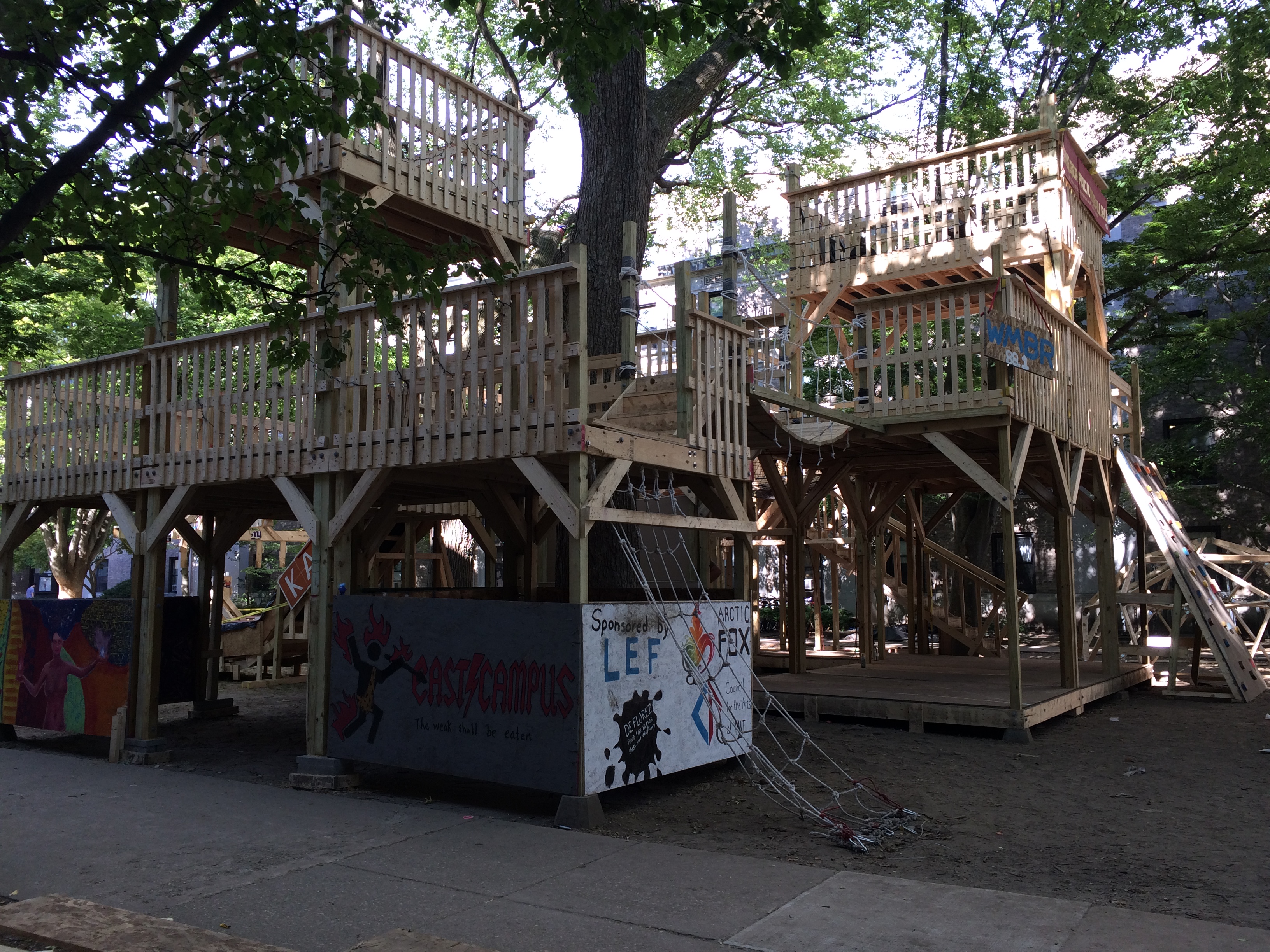
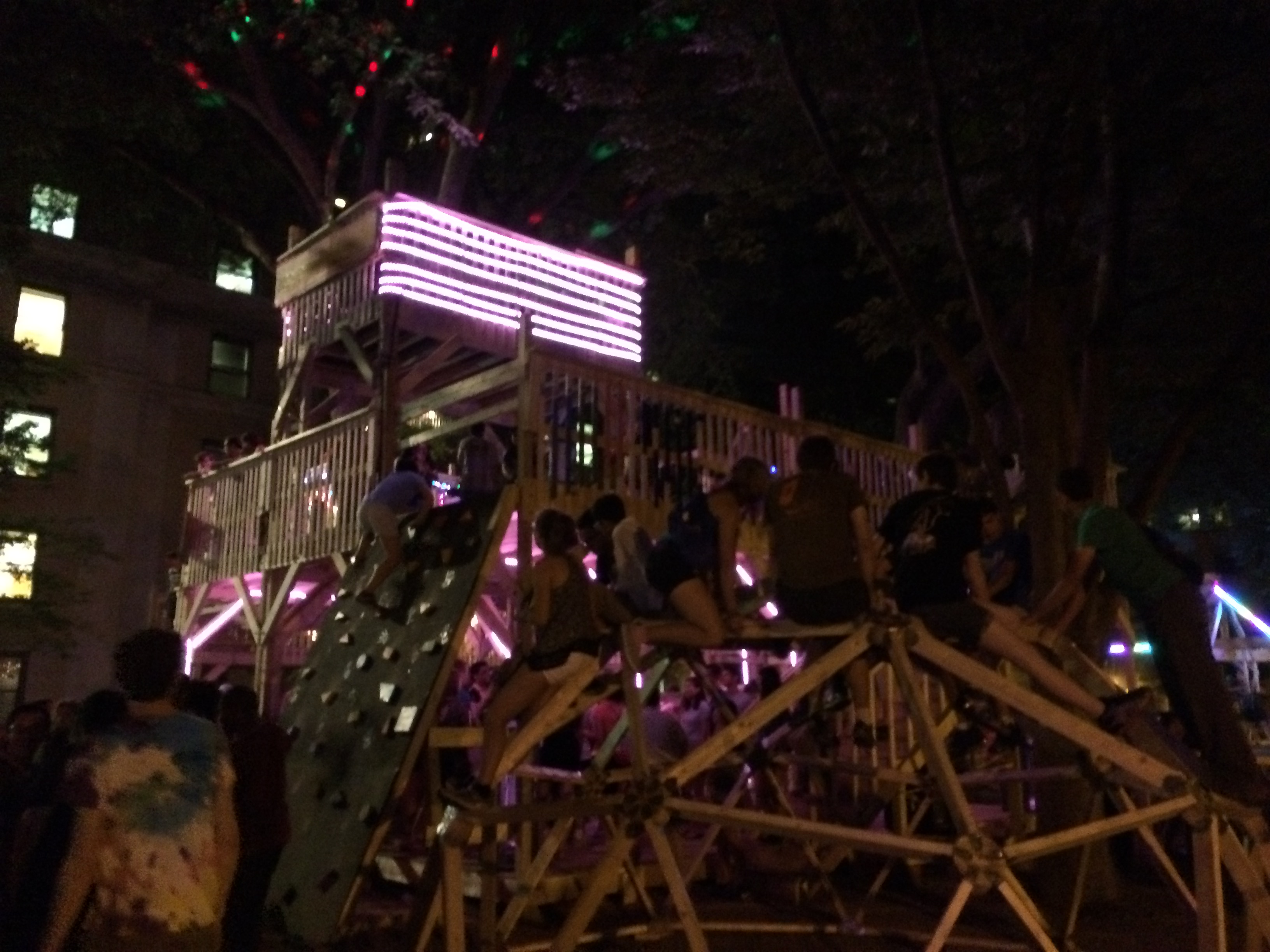
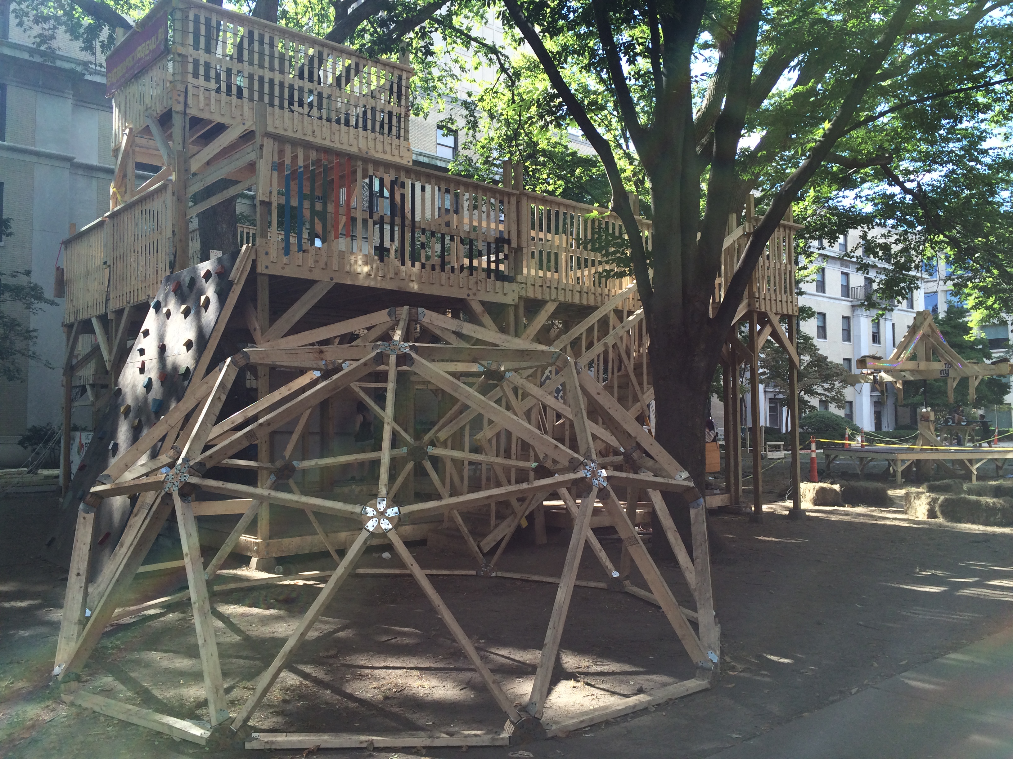
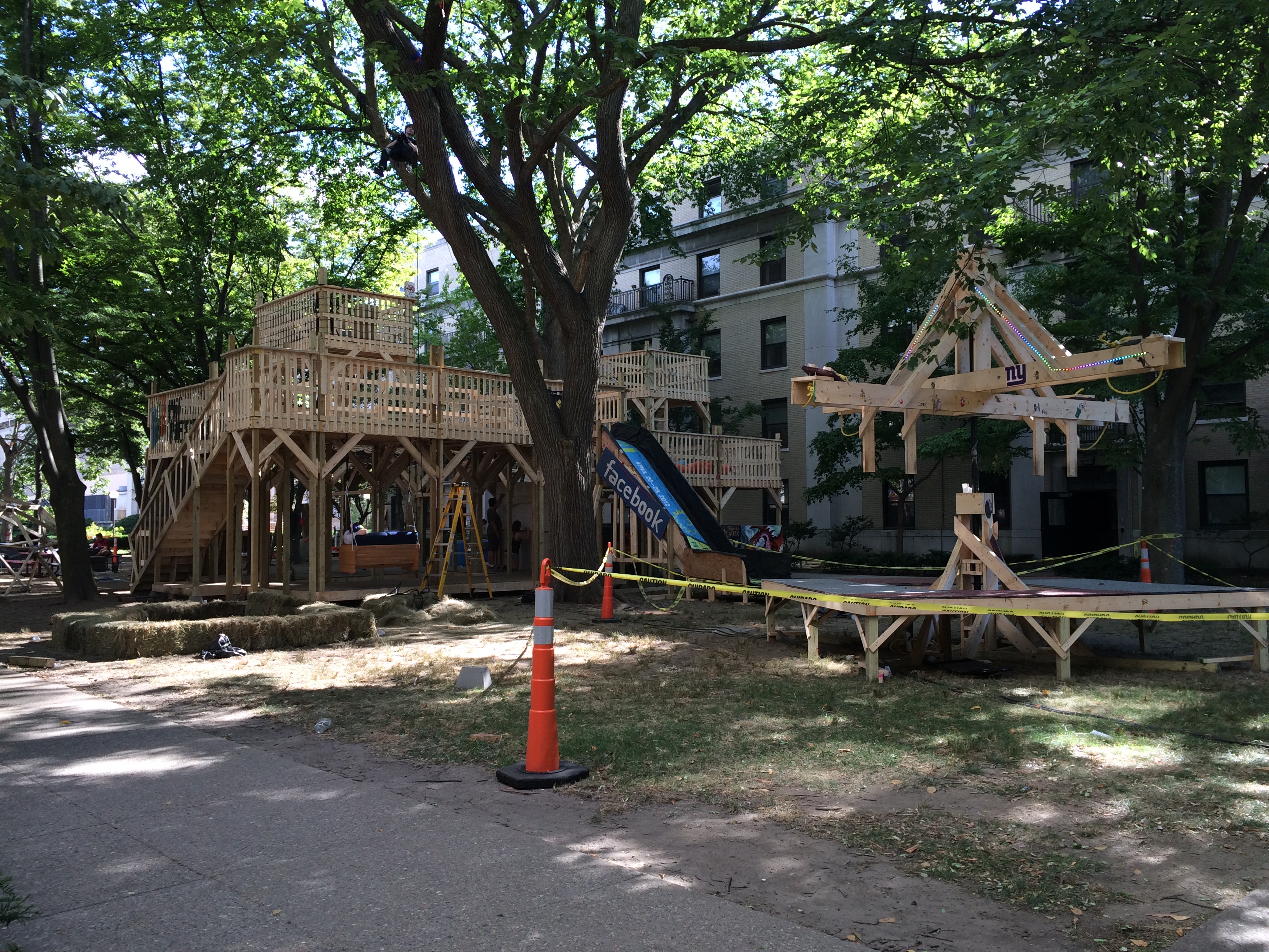
East Campus Dorm Rush 2016
Residential Exploration is a week during freshman orientation (mid-August) during which each of the dorms put together events/projects to show new students what their culture is like. This year (2016), I was on a team with Yanisa Techagumthorn and Henry Shackleton to organize this for my dorm, East Campus. We are known for our annual large amusement-park style projects, which in the past have included rollercoasters. Because of the scale of our projects, we started planning, contacting potential sponsors/applying for grants, and working with project teams leads in February.
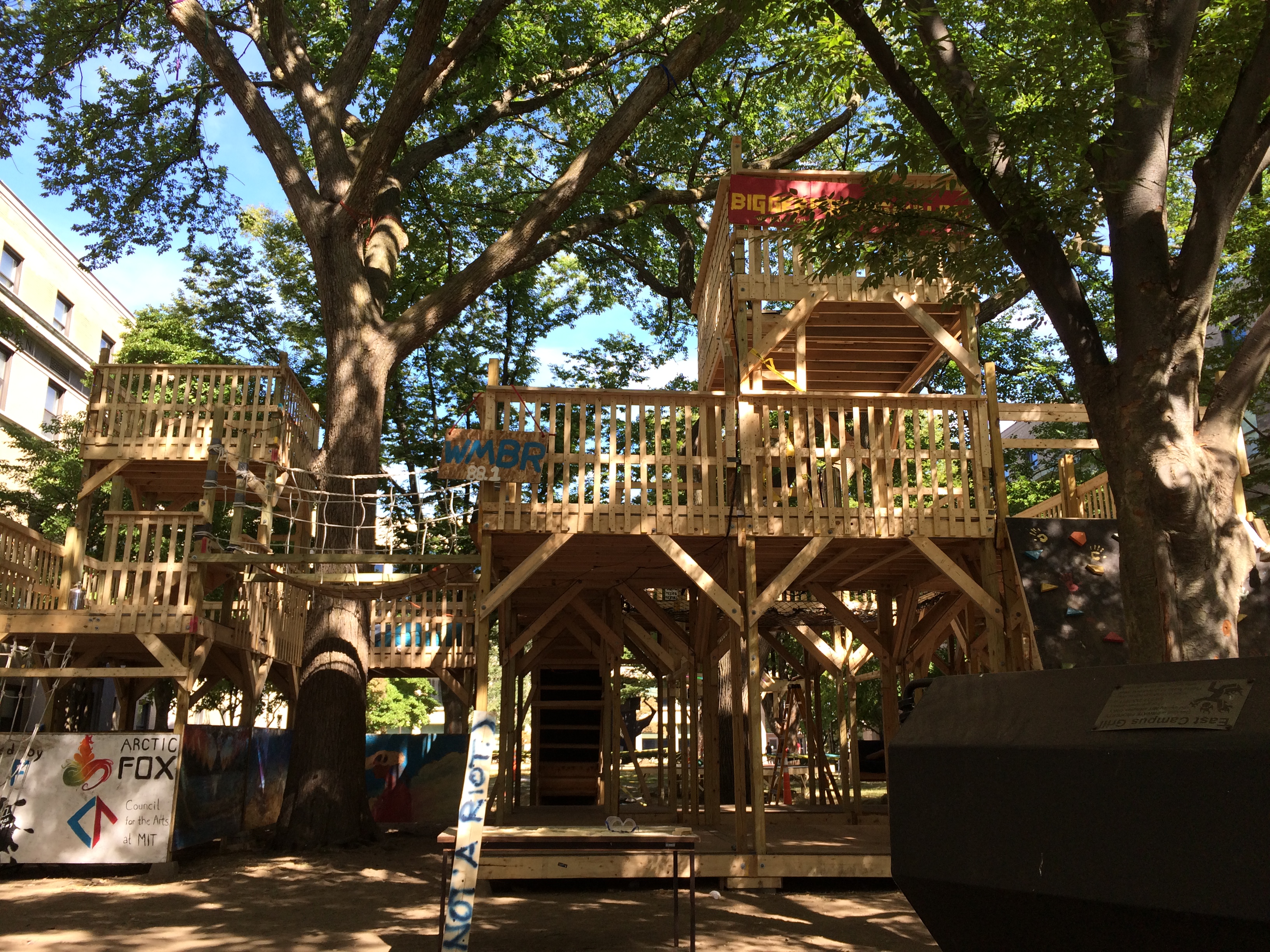
The general consensus of the dorm was that after two years of rollercoasters, we wanted to do something different--so the projects this year included multiple small amusement-park style rides (such as a swing carousel lovingly named #YOLO, a spinning see saw, and a flintstones-inspired car), and a large, three-story interactive fort with a slide and rock climbing wall.
We worked closely with EHS to ensure the safety of our construction site, and as a safety representative I actively monitored the safety of the site during construction as well. We also worked with MIT Facilities to get the fort designs approved by a licensed professional engineer and the City of Cambridge.
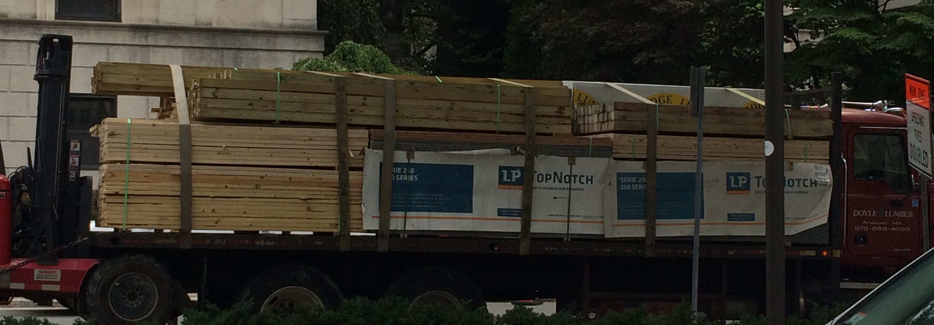
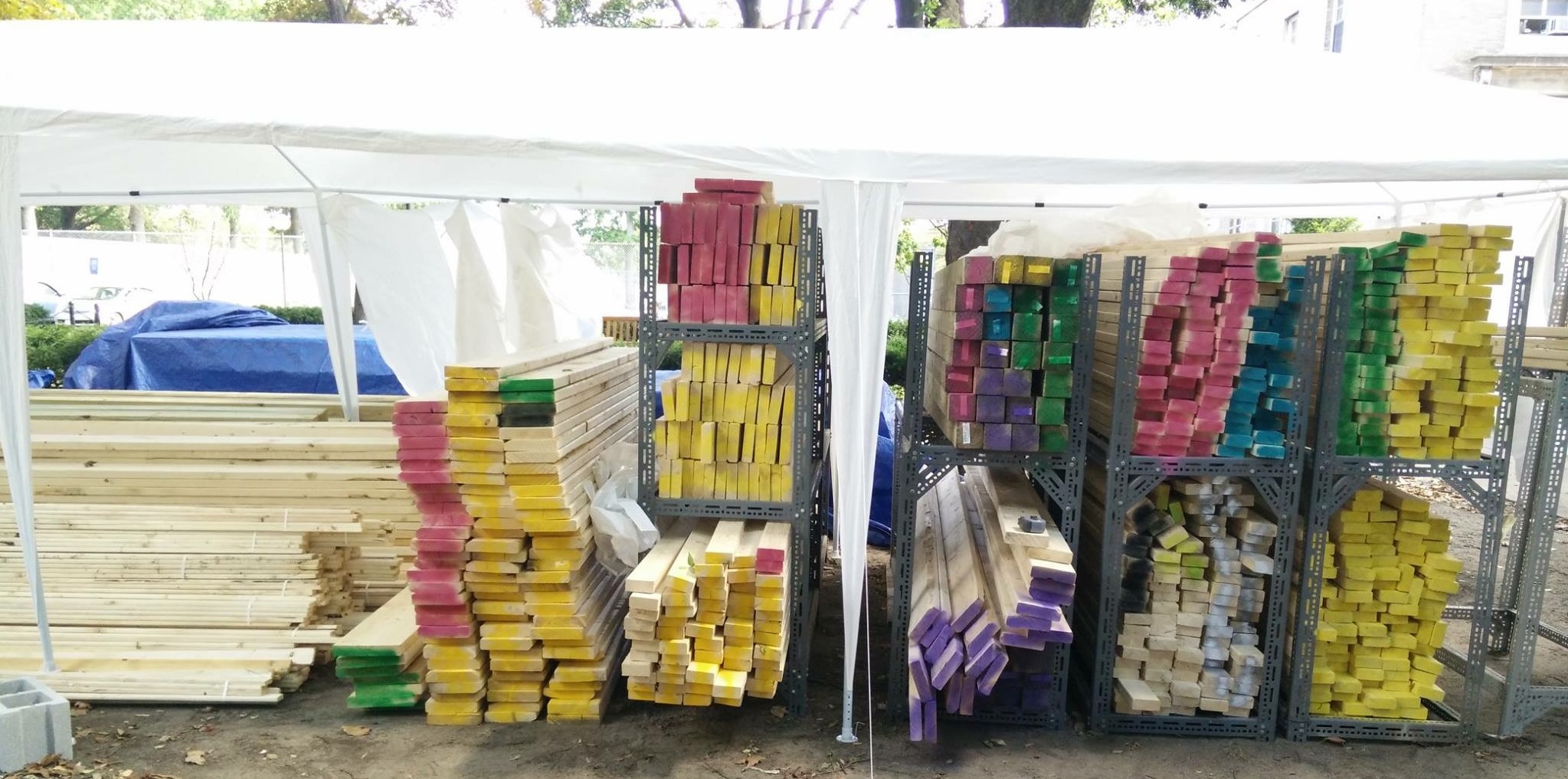
Overall, we had a budget of about $22,000, ~$7500 of which went to wood--which comes out to a lot, shown below. We spray painted the wood to mark them for the different teams.
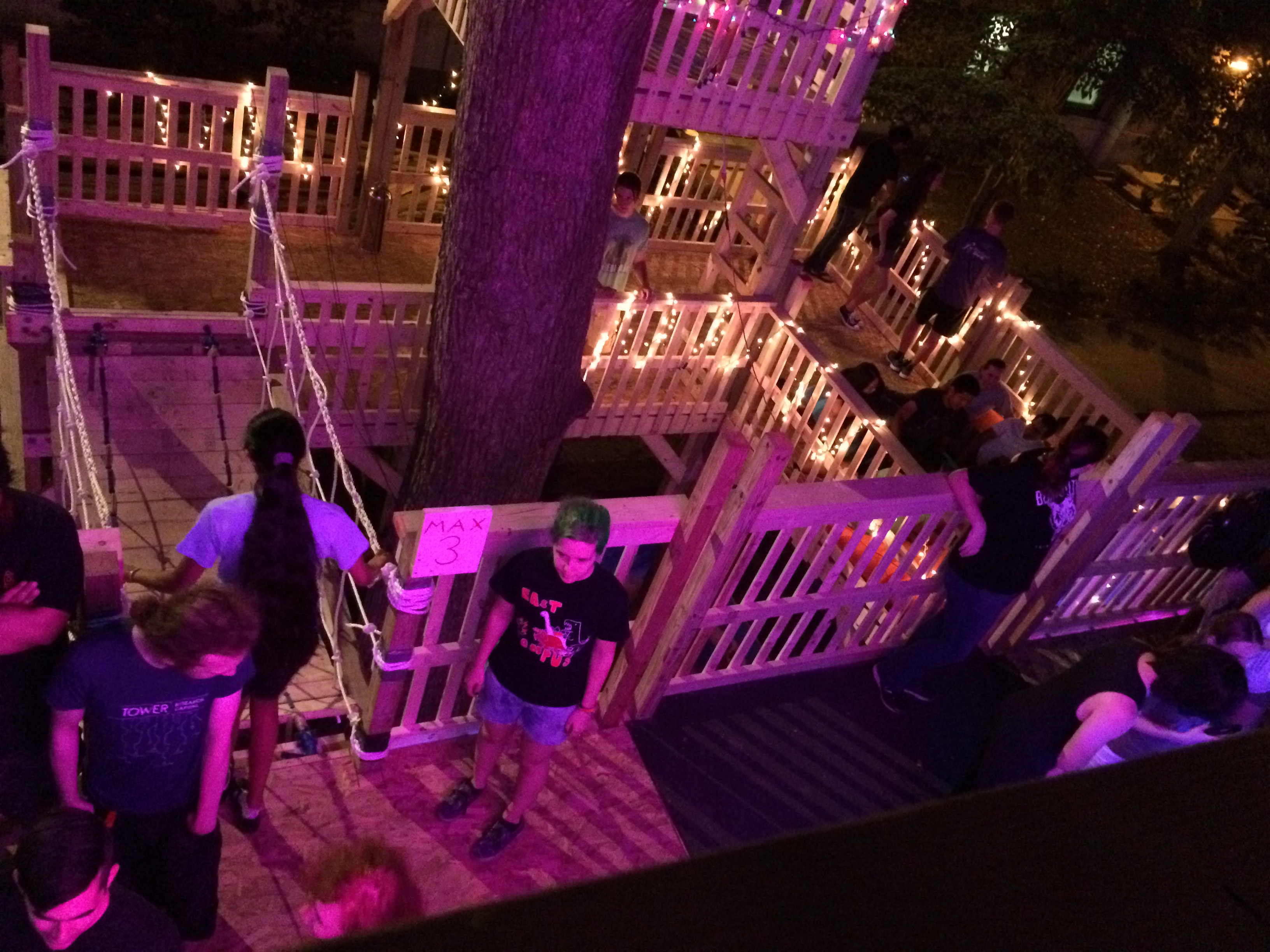
Over the next week, construction teams and freshmen helped turn the wood into fun structures. I had the pleasure of being able to help out with construction as well. During this time, students also put on many events for the freshmen, such as hair dying, basement bowling, finger painting, soldering seminars, and more. Banti Gheneti made a timelapse of construction, below.
Below are some photos of the final projects.
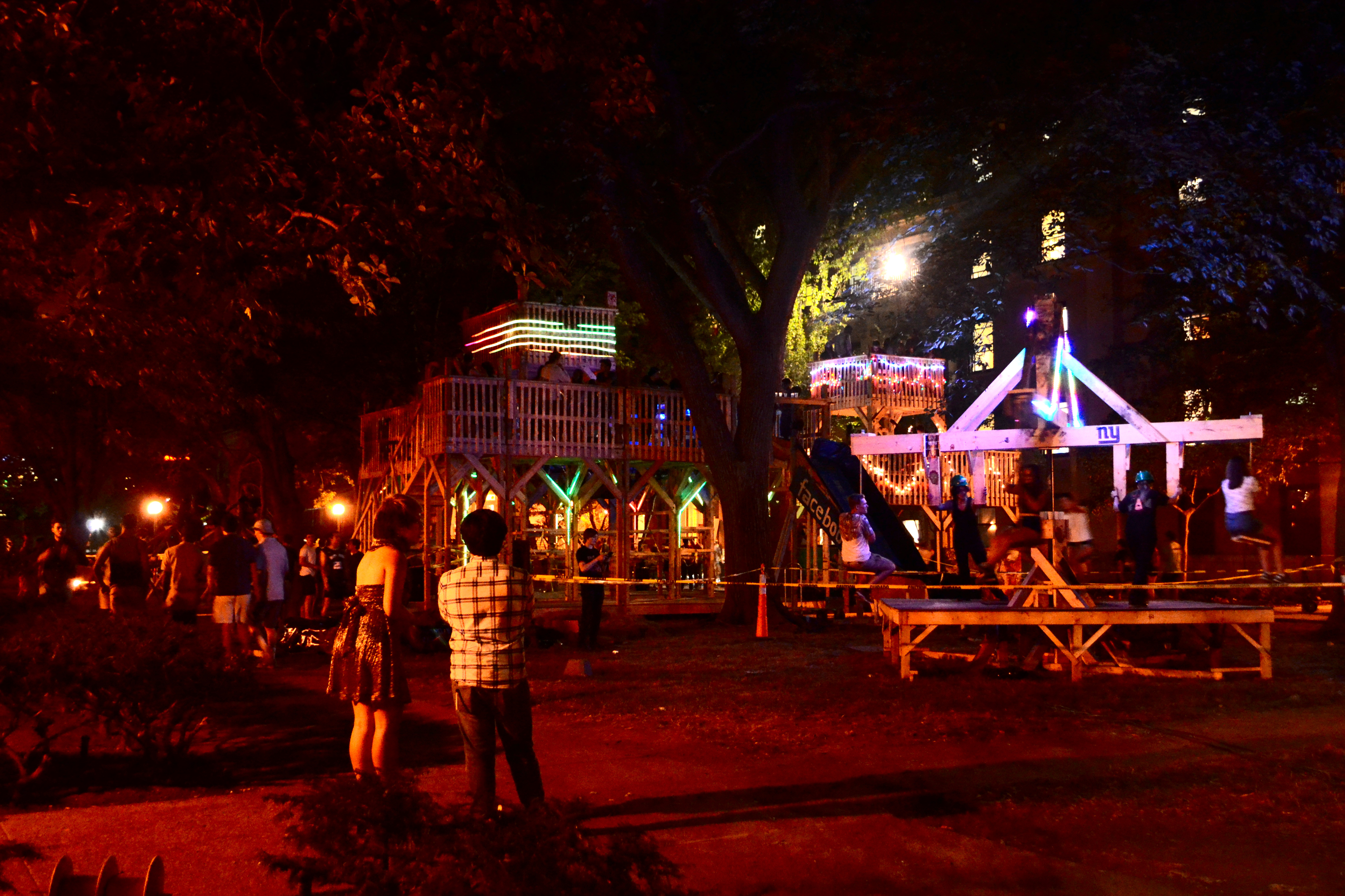
pc: Banti Gheneti.
 Back to portfolio
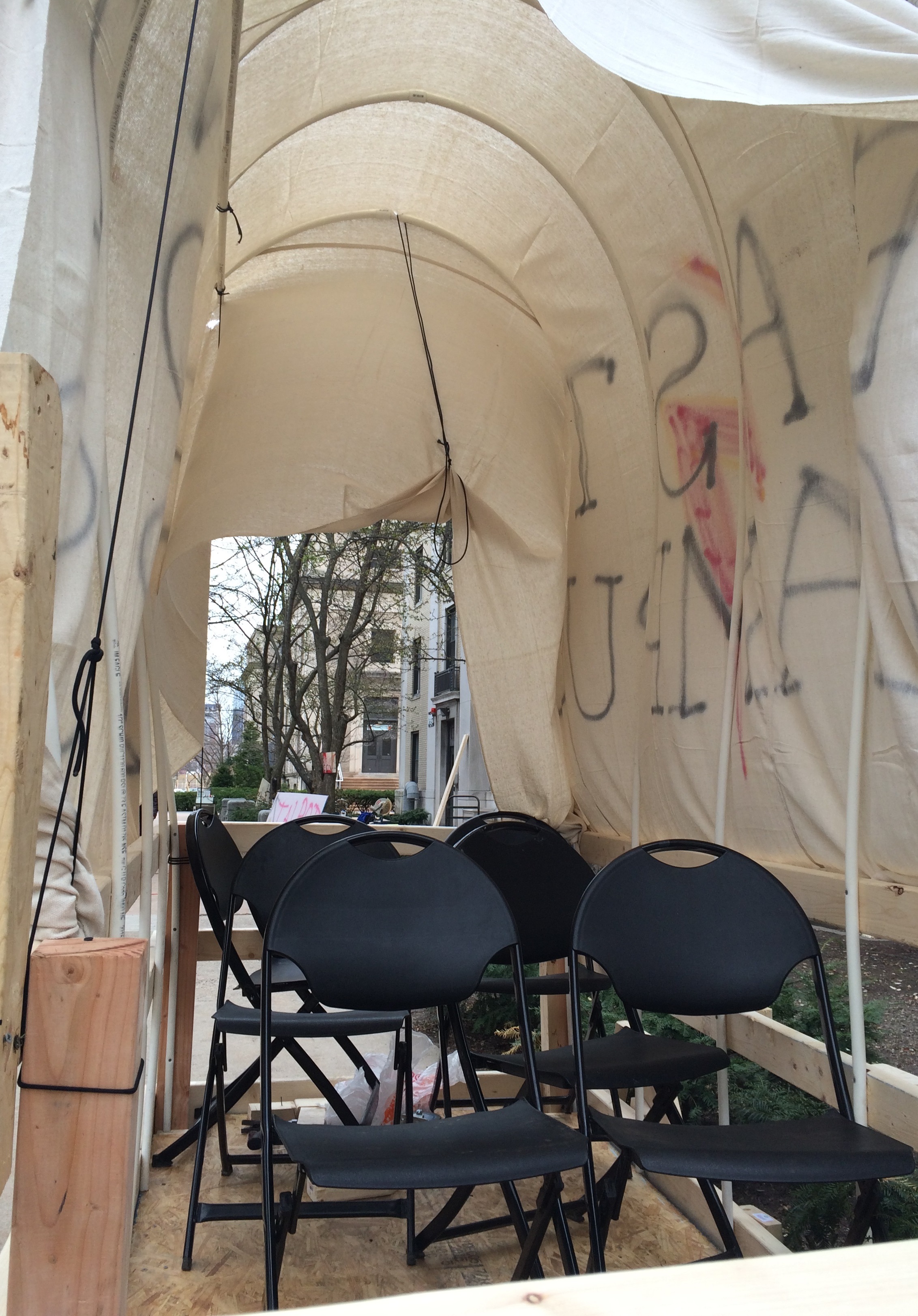
Covered Wagon
For Campus Preview Weekend, I co-led a seminar teaching visiting freshmen how to use power tools, followed by a fun hands-on project: building a covered wagon. We had a great to getting to know prospective students and also giving them a taste of the building resources/tools available to students in our dorm. After completion, we took the wagon accross campus for a ride (yes, it does roll, thanks to caster wheels).
Here are a couple photos!

Back to portfolio
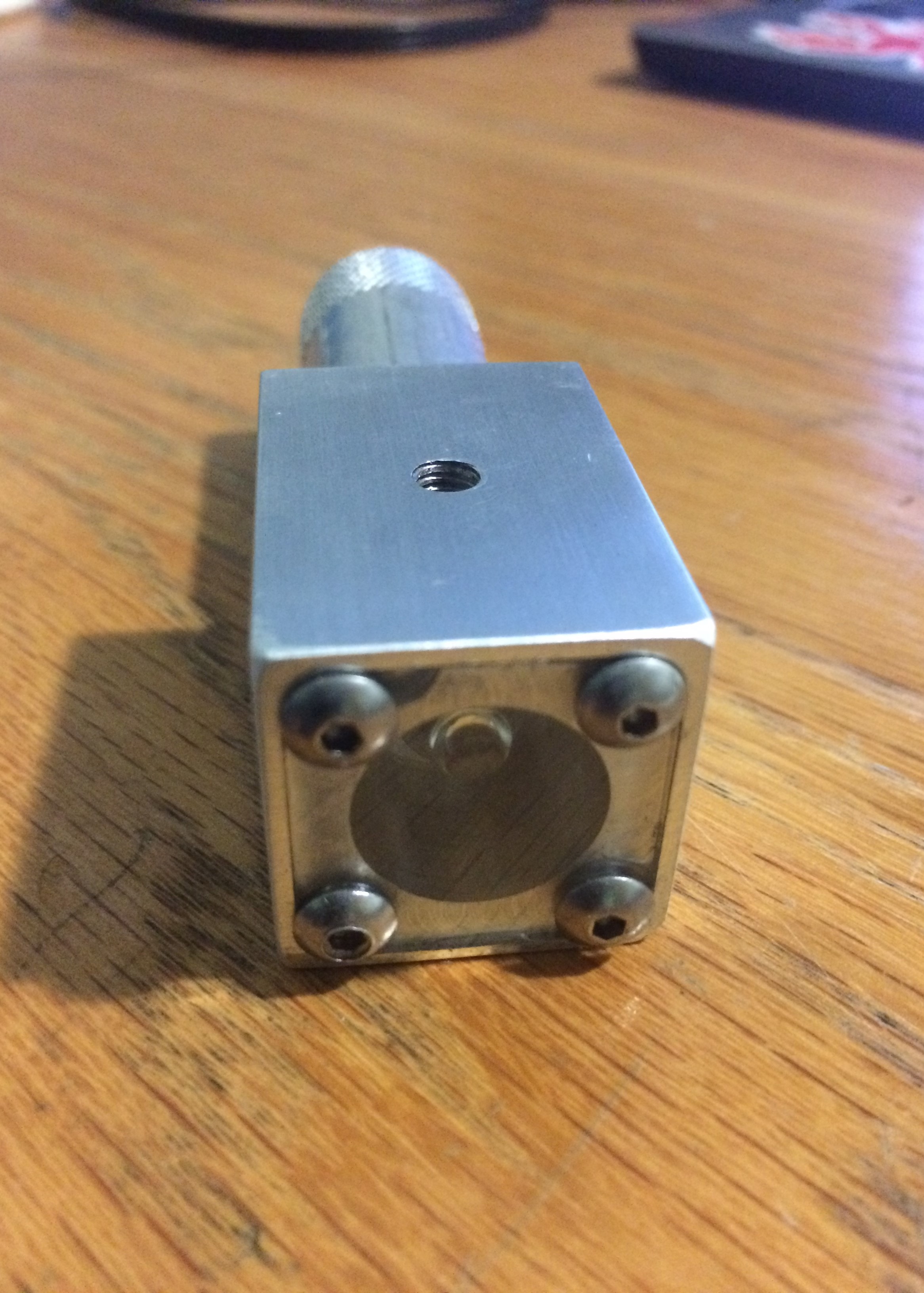
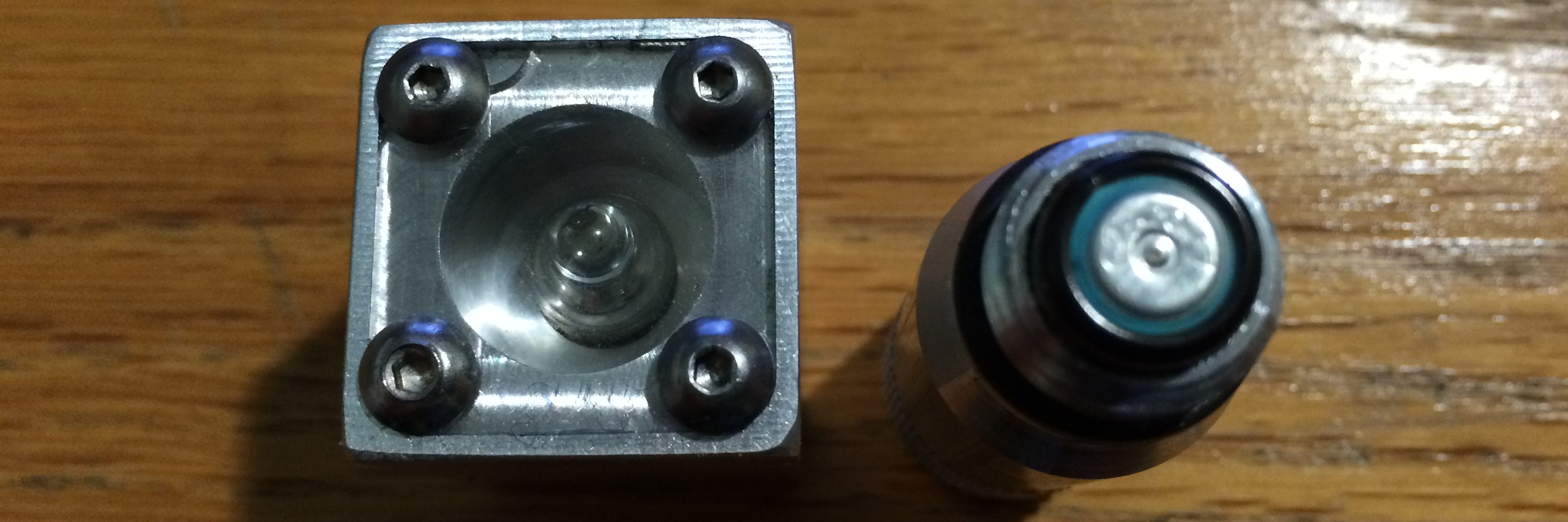
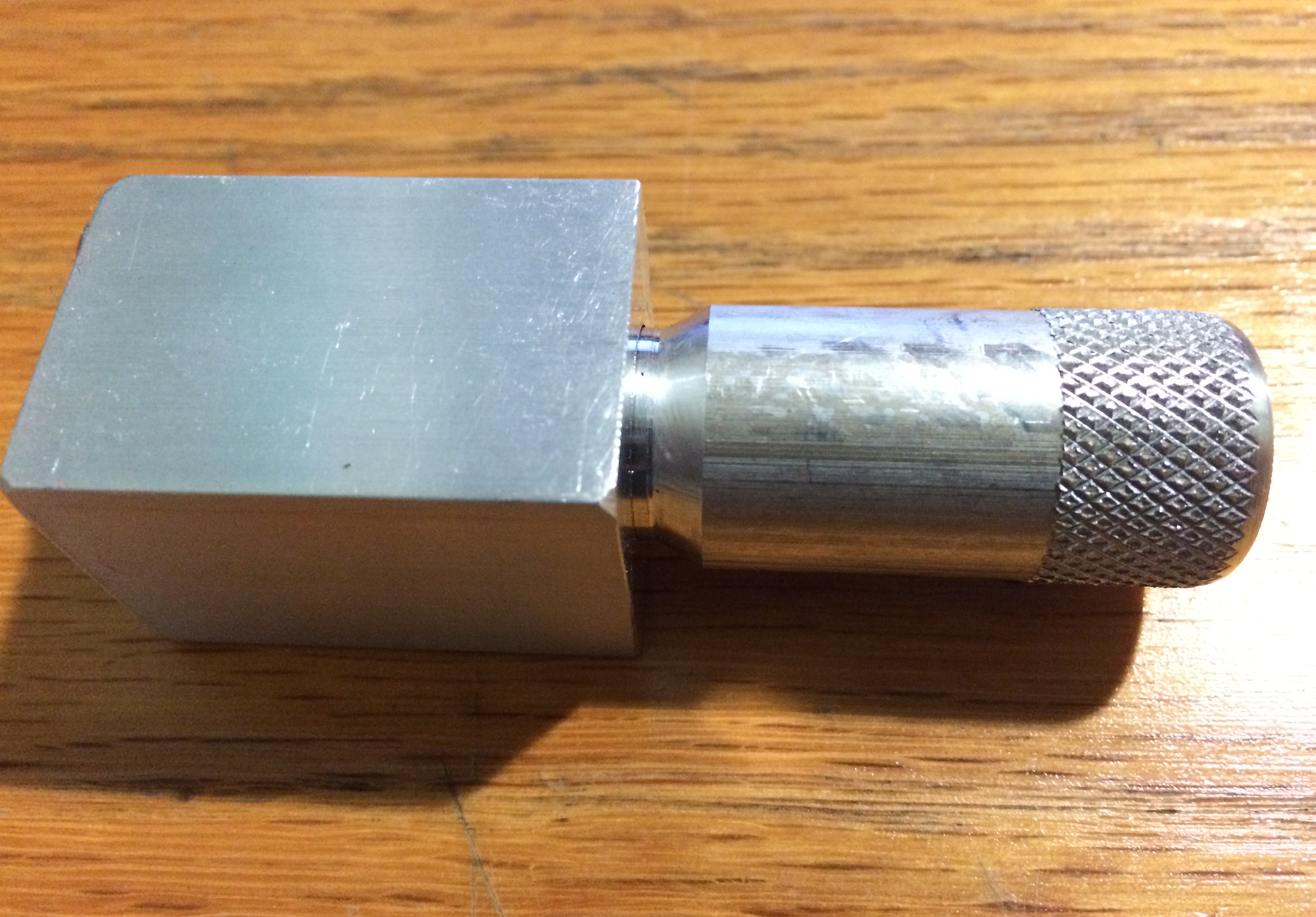
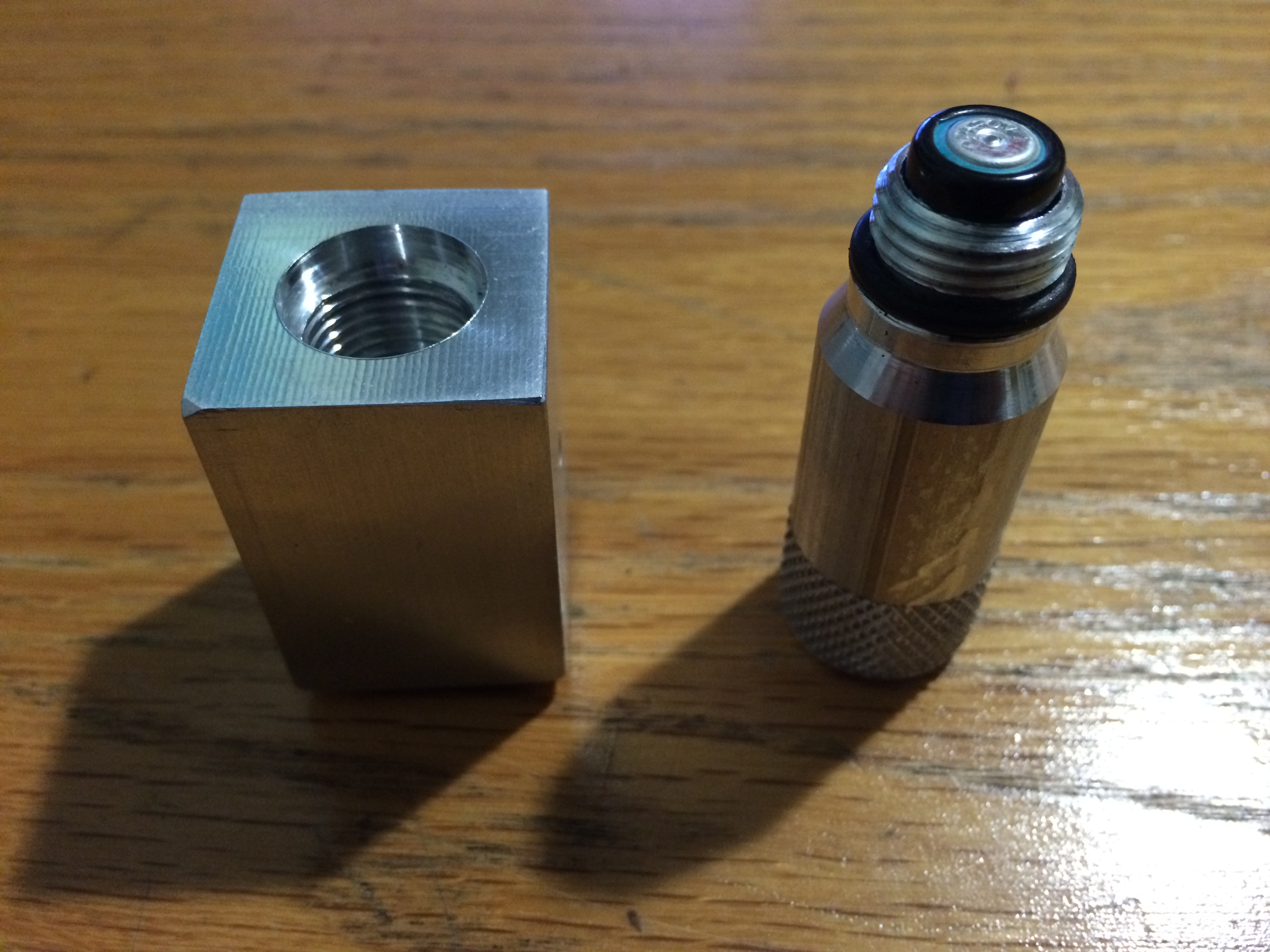
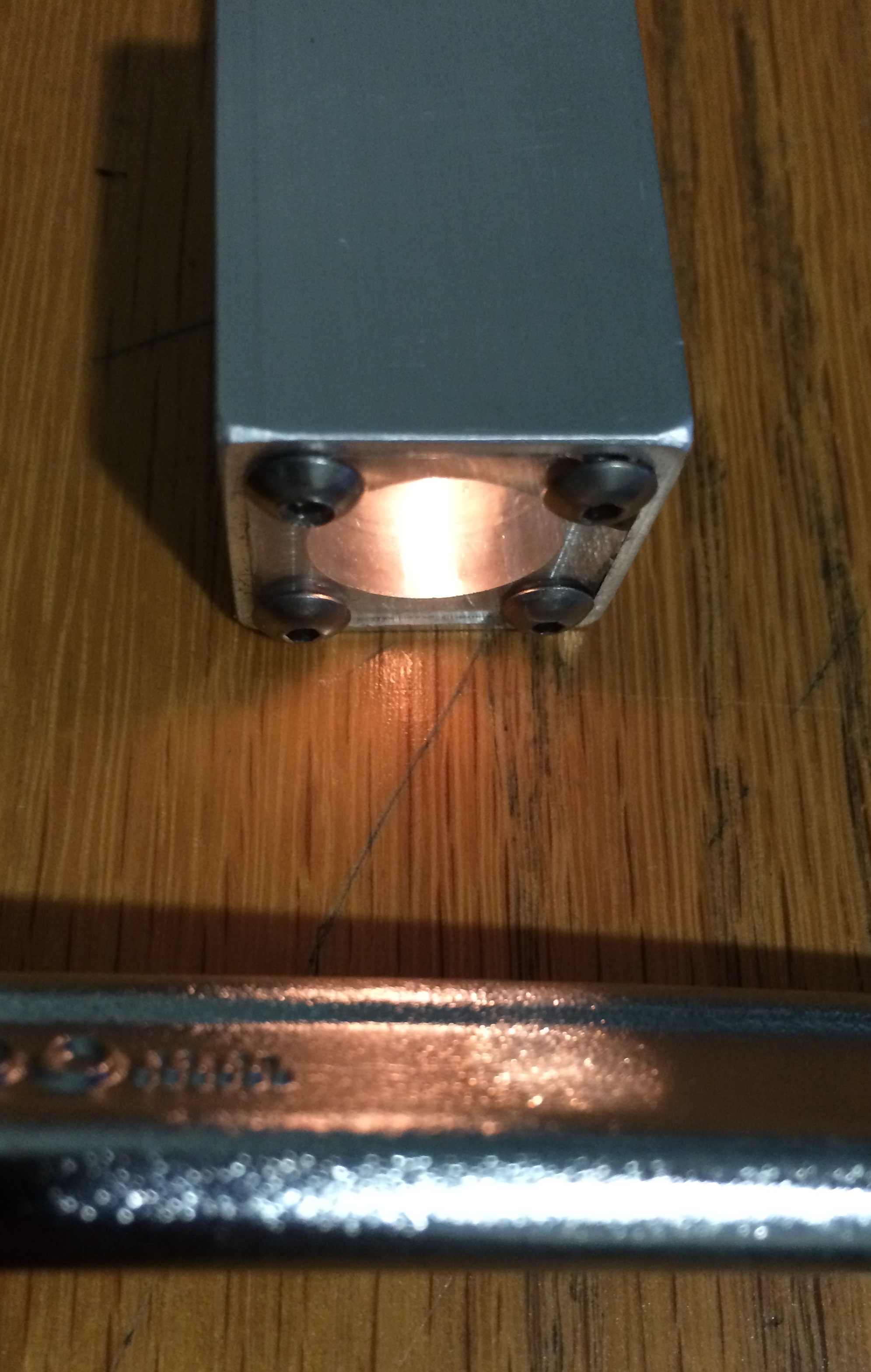
Machined Flashlight
For an introduction to machining class exercise, I made a flashlight using a mill and lathe. The square part was milled out to hold the lightbulb and screen, and the handle was turned to hold the battery. When the two parts are tightened, the lightbulb contacts the battery and completes the circuit, turning on. Here are some photos!
Back to portfolio
Line-Following Robot
I programmed an autonomous line-following robot with a partner for the final project of 2.678: Electronics for Mechanical Systems. On the last day, we raced our robot against all the other students in the class. We used photoresistors and an Arduino Nano. Our control scheme calibrated the readings from the photoresistors upon startup, and used both proportional control and conditionals.
Here's a video of our robot making it through some tricky paths to the finish line on competition day.
Back to portfolio
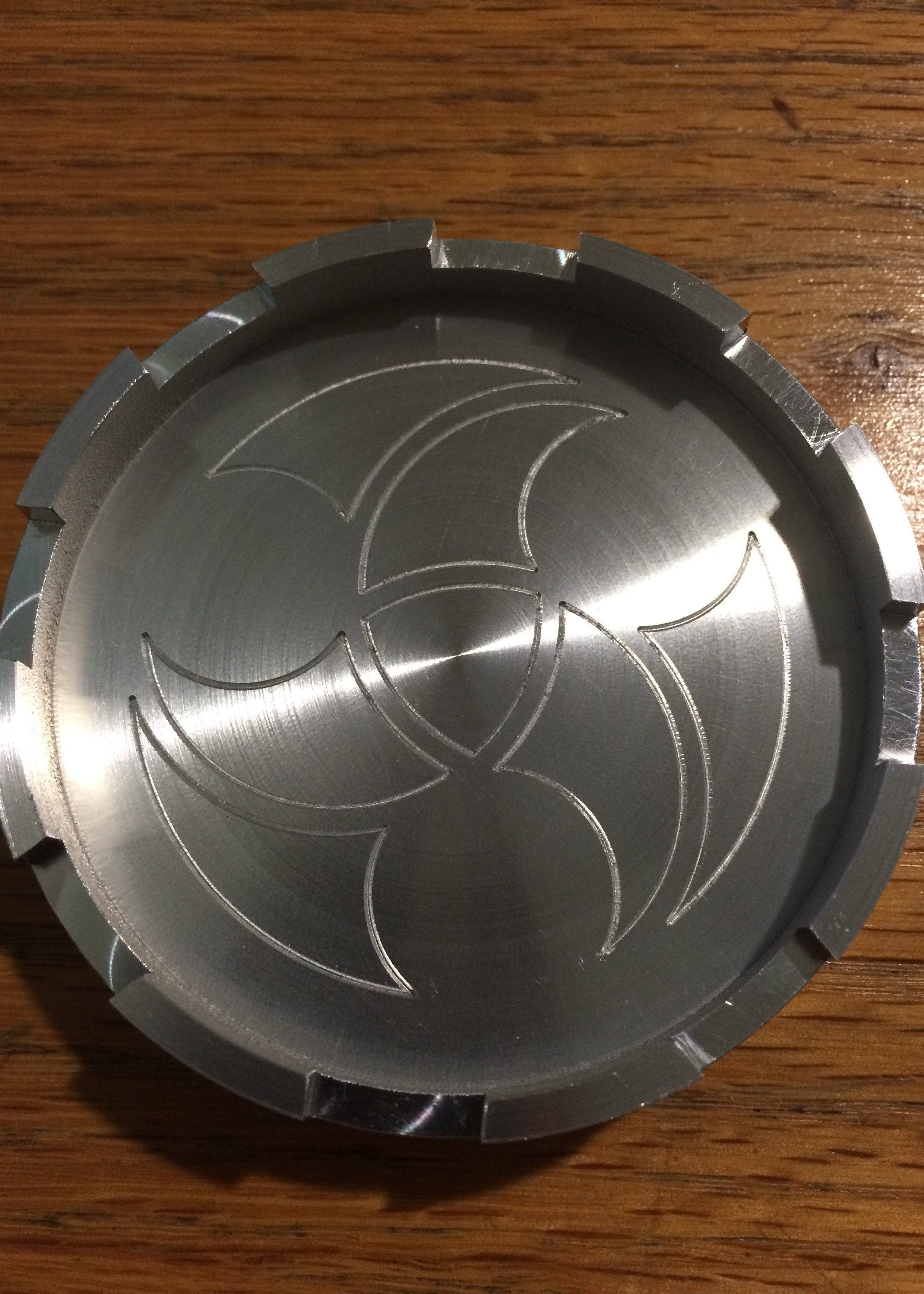
Paperweight
Revanth Damerla and I designed and fabricated a paperweight as part of 2.008, our design for manufacturing class. Below is a drawing of our original design. The concept was to have it be a cupholder in addition to a paperweight, with a castle rampart pattern on the rim and a geometric pattern in the cavity.
Our first step was turning on the CNC lathe, during which we bored out the cavity. We generated our toolpaths on MasterCam. The shop staff also put together a program for turning the bottom face of the paperweight such that it would spin. Here's a video of our two turned parts spinning, and a photo of the bottom face.

The next step was milling, during we machined the rampart pattern and did the engraving in the center. Unfortunately we had a 15-minute hard limit on the cycle time, so we didn't get to do some parts of the original engraving design. In retrospect we could have optimized the machining of the rampart pattern a little more and skipped the second pass we did for the engraving to save time, and completed the pattern.
Back to portfolio